- From the Assembly section of the action bar, click Make Component
 . . - In the dialog box:
- For Body or Feature Selections
 , select sketches, features, and bodies to include in the component. , select sketches, features, and bodies to include in the component. - Optional:
For Name, enter a name or leave blank to accept the default name.
- Optional: To specify the component coordinate system to be different from that of the current product:
- Click Coordinate System
 . . - Click in Origin Selection
 and then, in the 3D area, select a vertex, face, or circular edge. and then, in the 3D area, select a vertex, face, or circular edge.The Robot appears at the selected location. 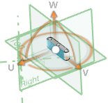 - To adjust the position and orientation of the coordinate system, do any of the following:
- Select reference items for X Direction Selection
 , Y Direction Selection , Y Direction Selection  , and Z Direction Selection , and Z Direction Selection  . . - Click Reverse Direction
 to reverse the direction. to reverse the direction. - Use the handles of the Robot to adjust the linear, rotational, and planar location of the coordinate system.
- Click
 . .
|