Overloading Element Properties | |||||
|
| ||||
- Right-click a section view, for example.
- Select Section view object > Overload properties.
The Characteristics dialog box appears.
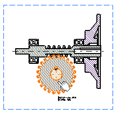
- In the view, select the element that you want to edit.
This element is highlighted in the drawing and listed in the Characteristics dialog box.

Important: You can also select several elements, if you want to overload their properties in the same way. In the case of several elements generated from a single part instance, all these elements are highlighted when you select one. You can select the elements in the 3D document, either by selecting a node in the tree or by multi-selecting the elements in the tree. - Select the element you want to edit in the dialog box and
click Edit.
In the Editor dialog box, you can modify the following parameters:
-
Cut in section views: Specifies that the 3D element will be cut in the section view, section cut or breakout view. Uncheck this option if you do not want an element to be cut in the view.
-
Use when projecting: Specifies that the 3D element will be projected in the view. Uncheck this option if you do not want an element to be represented in the view (other 3D elements possibly hidden by this element in the view will then be visible in the view).
-
Represented with hidden lines: Specifies that 3D hidden lines will be represented.
-
Shown: Specifies that the dress-up (color, line type, etc.) associated to the 2D generated element will be shown. The view is not re-computed.
- Projected as background: Sets the selected part as background. This helps in visualizing the other parts which are behind the selected part in the view. Note: If you have selected the shaded background mode for a view in which one of the parts is projected as background, then the shaded background mode becomes ineffective only for this part.
-
Graphic Properties area: Lets you modify graphic properties such as element color, line type and line thickness.
-
- Clear the Shown check-box and click OK.
In the view, the generated 2D element and the dress-up associated to it is no longer shown.
Note: If you select the Shaded Background Mode check box in Me > Preferences > App Preferences > 3D Modeling > Mechanical Systems
> Drafting > View section, under View generation, the generated 2D element is no longer shown. The shaded background remains unaffected.
 - In the tree,
select the PartBody.x node.
The elements of the part body are added to the Characteristics dialog box.
- Select the required elements in the list and click Edit.
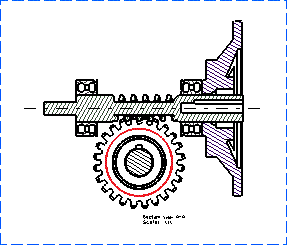
- In the Editor dialog box, select the red color
in the Graphic properties list and click OK.Note: The graphic properties cannot be applied to the hatching patterns.
- In the Characteristics dialog box, click
Apply.
The view is re-computed.

- In the tree, Ctrl + multi-select the 3D elements.
Back to the drawing, the elements have been added to the Characteristics dialog box.
- Select the required elements in the list and click Edit.
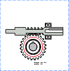
- In the Editor dialog box, clear the Shown
check-box and click OK.
- In the Characteristics dialog box, click
OK.
The selected element is hidden.
