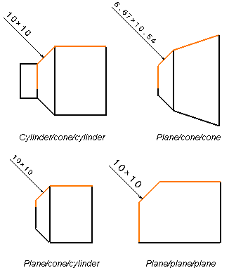
- In a Drawings context, you can create chamfer dimensions for the following types of cylindrical shapes:
cylinder/cone/cylinder, plane/cone/cone, plane/cone/cylinder, plane/plane/plane.

- When creating chamfer dimension on cylindrical shapes in a Drawings context, remember that:
- in the case of projection views, the projection plane needs
to be parallel to the cylinder axis.
- in the case of section views or section cuts, the section plane
needs to be parallel to, and to go through, the cylinder axis.
- the sketched profile on which the cylinder (or the cone) is
based must be a circle.
- All options defined in
> Drafting (Dimensions and Handles
tabs) are taken into account when creating chamfer dimensions.
- When editing chamfer dimension text properties (right-click and selectProperties >Dimension Texts tab), any information (for example associated
text, fake dimension, tolerance, text before/after, etc.) added to the
main value, will actually be positioned according to the first value
(excluding the "x" symbol, for example "19,1").
This information will be positioned in the following order: Text Before/Prefix/first
value/Tolerance/Suffix/Text After/second value (including the "x" symbol,
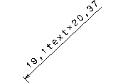
for example "x 20,37"). An example is provided below, with a Text After.

- When re-routing chamfer dimensions which have only two reference
elements (the element to be dimensioned and a single reference line
or surface), you will need to select three reference elements.
|

