Analyzing View Geometries

You can analyze view geometries to diagnose a sketch.

For example, if a sketch contains inconsistent geometry, you neither can drag the geometry, nor change it in any way. Therefore, you can find it useful to analyze geometry in an active view through various means.

This task shows you how to:


Before you begin:
  • By default, the Sketch Solving Status command is not available in any of the action bars. To make it available, you need to customize the action bar.
  • Open a drawing representation.
  • Go to Me > Preferences > App Preferences > 3D Modeling > Mechanical Systems > Drafting > Geometry section, and select the Create detected and feature-based constraints check box or from the Sketch section of the action bar, click Create Detected Constraints .

Use the Sketch Solving Status

This is a quick way to analyze a sketch and detect whether it is under-constrained or over-constrained.

  1. Select all the circles.
  2. From the Sketch section of the action bar, click Constraints Defined in Dialog Box .
  3. In the Constraint Definition dialog box, select the Fix check box, and then click OK.
    The geometry color turns to green indicating that the view geometries are iso-constrained.
  4. Select the two vertical parallel lines.
  5. Click Constraints Defined in Dialog Box and select the Fix and the Vertical check boxes.
    The geometry color turns to green indicating that the view geometries are iso-constrained.
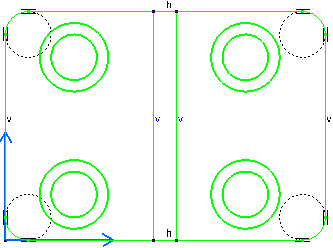
  6. Click OK.
  7. From the customized section of the action bar, click Sketch Solving Status .

    For more information, see Customizing an Action Bar by Adding Commands.

    This command gives you a quick diagnosis of the geometry status.

    The Sketch Solving Status dialog box appears and informs you of the general geometry status, whether it is under-constrained, over-constrained or iso-constrained.

    Meanwhile, the information given in the Sketch Solving Status dialog box is highlighted in the work area and the element that are under-constrained are highlighted too.

    In this case the four points are highlighted indicating that they are under-constrained.


Use the Sketch Analysis

This method gives the detailed analysis of a sketch. It provides the status of each element and the constraint of the sketch. It allows you to hide constraints, create geometry, and visualize use-edges in the sketch. You can deactivate, isolate, delete and also replace a 3D geometry.

  1. From the Sketch section of the action bar, click Sketch Analysis .
    The Sketch Analysis dialog box contains three tabs: Geometry, Use-edges and Diagnostic.

    Construction elements appear in blue in the geometry.

    Note that you can sort the displayed elements in the dialog box by Name, status or Type, by clicking the appropriate tab. You can also select elements from the dialog box and they will be highlighted in the work area.

  2. Select the Geometry tab to display information about all the connex profiles in the view.
  3. Click the Diagnostic tab.

    It gives information about every element of the geometry or constraint of a view.

    For more information, see Sketch Analysis.

  4. Click Hide Construction Geometries .
    All the construction elements are hidden from the dialog box.

    If you select items from the Detailed Information table, they will be highlighted in the view, enabling you to identify them easily. To solve constraint-based problems in the view, you need to edit the geometry directly.

    • Driving dimensions use invisible constraints to drive geometries. So these constraints appear in the Diagnostic tab, but are not highlighted in geometry of the view because they are invisible. If such dimensional constraints (invisible constraint created for driving dimension) are deleted in the Diagnostic tab, then the dimension will turn not up-to-date. The dimension must be manually deleted.

Analyze Sketch for Design Range

You can analyze if an element in the sketch is beyond the design range of the model.

  1. click Sketch Analysis .
    appears.
  2. In the Sketch Analysis dialog box, click the Diagnostic tab.
  3. Under Detailed Information, the Scale check of each element is listed. Scale check can be:
    • Valid: inside limits: For the geometric elements within size limits and with correct positioning.
    • Invalid: exceeds limits: For the geometric elements beyond the size limits of the design range. It is also applicable for elements which are positioned so far from the origin that they fall outside the footprint. If you exit Sketcher, without scaling down these elements within the size limits of the model, a warning message appears in 3D prompting the same.
    • Ignored: not applicable: For the elements that do not appear in 3D such as construction elements, or constraints.
    • ???: For the elements whose status cannot be computed. This is an undesirable status.
  4. Resolve errors for invalid elements, if any.