 -
From the
Assembly section of the
action bar, click
Assembly Feature
 . .
The Assembly
Features dialog box appears.
-
Select the
Functional Plastic Parts
pattern specification in the
tree.
Rectangular Pattern.1 name is displayed in the Shape box.
-
Select the representation in the tree that will be affected
by the pattern: ASD_Block_Representation.
-
Click OK in the Assembly
Features dialog box.
- An Assembly Feature node is created under the active product, and containing an Assembly Hole feature.
- The contextual symbol appears on the affected representation:
 . .
-
From the
standard area
of the
action bar,
click
Update
 . .
The pattern of tapped holes is applied on the affected representation. 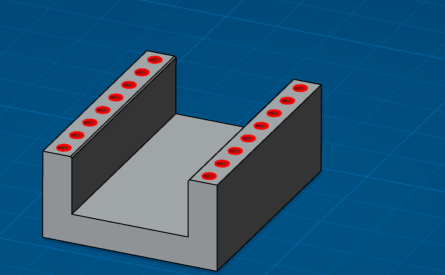
-
Double-click the affected representation in order to switch in Part Design app.
Note:
- Double-clicking a representation in the
tree
lets you switch to the last recently opened representation app.
- If needed, from the
Compass,
click
3D Modeling
Apps
and select
Part Design.
-
Right-click the PartBody of the affected representation and select Create Technological Results... from the contextual menu.
A Technological Results node is created under the
PartBody of the affected representation. This node contains all features needed to define the pattern of tapped holes in the affected representation: hole and thread features.
-
From the Review section of theaction bar, click Tap - Thread Analysis
 . .
The
Thread/Tap Analysis dialog box appears. Note:
16 taps have been detected.
-
Click Apply in the
Thread/Tap Analysis dialog box.
Tapped hole information is displayed. 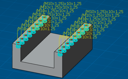
-
Click OK in the
Thread/Tap Analysis dialog box.
-
Double-click the root product to back in Assembly Design app if needed.
|