Creating a Positioned Sketch

You can create a positioned sketch.

In positioned sketch, you specify the reference plane, the origin, and the orientation of the absolute axis. The positioned sketch ensures associativity with the 3D geometry (especially Power Copies and UDFs).

It enables you to explicitly define (and later change) the position of the sketch absolute axis. This offers the following advantages:

  • You can use the absolute axis directions like external references for the sketched profile geometry.

  • When the geometry of the 3D shape evolves and the associated position of the sketch changes, the shape of the sketched profile (2D geometry of the sketch) remains unchanged (even if the sketched profile is under-constrained).


Before you begin: Insert in an assembly a simple 3D shape similar to the one below. You are going to create a positioned sketch that will enable you to design the retaining bracket for this 3D shape.
  1. From the Assembly section of the action bar, click Click Positioned Sketch .
  2. Click Create new in the Choose a 3DShape dialog box.

    In the Choose a 3D Shape dialog box:

    • The Product box displays the name of the active product.
    • 3DShapes either lists the available 3D shapes instanced under the active product or lists the available 3D shapes instanced under a selected product. In both cases, these 3D shapes can be modified.
    • The Create new command allows you to create a 3D shape.
      Important: When you create a new 3D shape in Assembly commands context, its Nature is set as Specification whatever your choice in the dialog box, and you cannot change the nature of this 3D shape after it has been created with this command. See Nature of a New 3D Shape Created in Assembly Commands Context.
    • The Automatically create new 3D Shape when none exists option allows you to create a 3D shape either under the active or selected product automatically. In this case, the Choose a 3D Shape dialog box does not appear.

    The New Content tab appears.
  3. Click OK in the 3D Shape dialog box.

    The Sketch Positioning dialog box appears.

    Position the sketch absolute axis as follows:

    • Its origin is on the axis of revolution.
    • Its horizontal (H) direction is parallel to the flat face.
    • Its vertical (V) direction is normal to the flat face.

  4. Move the pointer over the pad if you want to select the plane as you would do for a sliding sketch.
  5. Deactivate the Smart Mode to select the support manually.
    Important: You can choose the type of support between two options: positioned or sliding.
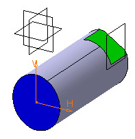
  6. Select the origin and orientation of the sketch.
  7. Click to activate the Smart Mode for any of them to move the pointer over the pad and choose either the origin or the orientation.
    The absolute axis of the sketch is now positioned on this axis. Its orientation has not changed.

  8. Select Parallel to line in the Type box in the Orientation tab to specify the absolute axis orientation according to an edge of the flat face.
  9. Select an edge of the flat face.
    The absolute axis of the sketch is now oriented like the selected edge.

  10. Optional: Invert the H direction and make the V direction normal to the flat face:
    1. Click V Direction in the Orientation tab to specify that you want the orientation to be defined according to the V direction.
    2. Click Reverse V to revert the V direction.
    3. Click Swap to swap H and V directions.
    The sketch is now positioned as wanted.
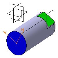
  11. Click OK.
    You are now in the Sketcher app and ready to sketch a profile for the retaining bracket.

    Note: In this scenario, you did not create any constraints on 2D geometry. The geometry is therefore under-constrained. Yet, if you move or resize the 3D shape (no matter how significantly), the profile you sketched will remain absolutely unchanged. Its shape will not be altered as the position of its absolute axis is explicitly defined, it is automatically pre-positioned in 3D before its 2D resolution.
  12. To generate a library from any sketch while editing it, perform the following steps:
    1. From the Add menu, select Generate > Generate Library.
    2. In the Create Library dialog box, specify a name for the library and click OK.

      Note: The sketch should be saved in the database and the library name should be unique.

    3. Create a new 3D part using this sketch.
    4. From the Tools section of the action bar, click Library Browser.
    5. Expand the library classes, select an appropriate item, and then click Instantiate on the context toolbar.
    6. Click in the 3D area to position the group of geometries resulting from the library linked to the sketch.
  13. Click Exit app .
    You are now back in Assembly Design app.