Enriching an Existing Engineering Connection | ||||||
|
| |||||
-
Double-click an existing engineering connection in the tree.
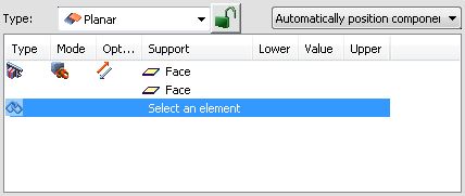
The Engineering Connection Definition dialog box appears containing one constraint.
-
From the
Assembly section of the
action bar,
click
Engineering
Connection
 .
An empty Engineering Connection Definition dialog box appears.
.
An empty Engineering Connection Definition dialog box appears. -
In the work area, select two geometric elements to be connected in the same components as
those involved in the existing engineering connection.

Since an engineering connection already exists between the selected components, the Choose Connection dialog box appears and displays the list of existing engineering connections. -
Select the engineering connection to enrich and click
Enrich.
Note: To create a new engineering connection, click Create New.

The Engineering Connection Definition dialog box disappears during this operation. -
Click OK.
The new constraint is added to the engineering connection in the Engineering Connection Definition dialog box.

-
Click
OK
in the
Engineering Connection Definition dialog box.
Important: During engineering connection creation, while the Positioning Mode option is on
 , no engineering connection is created when clicking
OK in the
Engineering Connection
Definition dialog box.
, no engineering connection is created when clicking
OK in the
Engineering Connection
Definition dialog box.
The Positioning Mode option is not available during engineering connection edition.