Creating User Patterns using Single Elements | |||
| |||
-
From the
Assembly section of the
action bar, click User Pattern
 .
The Choose a 3D Shape dialog box appears.
 -
Click Create
new in the Choose a
3DShape dialog box.
In the Choose a 3D Shape dialog box:
- The Product box displays the name of the active product.
- 3DShapes either lists the available 3D shapes instanced under the active product or lists the available 3D shapes instanced under a selected product. In both cases, these 3D shapes can be modified.
- The Create
new command allows you to create a 3D shape.
Important: When you create a new 3D shape in Assembly commands context, its Nature is set as Specification whatever your choice in the dialog box, and you cannot change the nature of this 3D shape after it has been created with this command. See Nature of a New 3D Shape Created in Assembly Commands Context. - The Automatically create new 3D Shape when none exists option allows you to create a 3D shape either under the active or selected product automatically. In this case, the Choose a 3D Shape dialog box does not appear.
The New Content tab appears. - Click 3D Shape under Physical Product Structure node in the New Content tab.
-
Click OK in the 3D Shape dialog box.
The new 3D Shape is created under the active product.
| Important: You switch from Assembly Design app to the last representation app you used. |
- Select the element you want to replicate as a pattern.

Note: When you are using a feature list, you need to multi-select the features in the order they were created.The User Pattern Definition dialog box appears.
Important: The Keep specifications option is disabled for Feature lists and Patterning patterns. - Select the sketch needed to position the pattern and
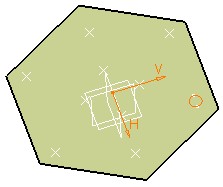
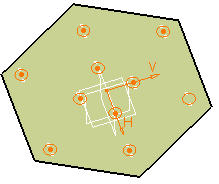
click Preview.
It includes the points you need to locate the duplicated pockets.

-
If you need less points, click the points you do not need to deselect them.

Anchor: By default, the app positions each instance with respect to the center of gravity or the element to be duplicated. To change this position, use the anchor box: click the Anchor box and select a vertex or a point.Note: Commands for creating the anchors you need are available from the context menu of the Anchor box:- Create Point: for more information, see Creating Points.
- Create Midpoint: creates the midpoint of the line you select.
- Create Endpoint: creates the endpoint of the line you select.
- Create Intersection.
- Create Projection.
If you create any of these elements, the app then displays the corresponding icon next to the Anchor box. Clicking this icon enables you to edit the element.
-
Click OK.

Important: - Patterning User Features (UDFs) is not allowed.
- You cannot cut nor copy user patterns.
- You come back in the Assembly Design app.