Create an Axis System from Coordinates and Geometry
-
From the
Assembly section of the
action bar,
click Axis System
 . .
The Choose a 3D Shape dialog box appears.
-
Click Create
new in the Choose a
3DShape dialog box.
In the Choose a 3D
Shape dialog box:
- The Product box displays the name of the active product.
-
3DShapes either lists the
available 3D shapes instanced under the active product or lists the available 3D shapes
instanced under a selected product. In both cases, these 3D shapes can be modified.
- The Create
new command allows you to create a 3D shape.
- The Automatically
create new 3D Shape when none exists option allows you to create a 3D
shape either under the active or selected product automatically. In this case, the
Choose a 3D Shape dialog box does not appear.
The New Content tab appears.
-
Click 3D Shape under Physical Product
Structure node in the New Content
tab.
-
Click OK in the 3D Shape dialog box.
The new 3D Shape is created under the active product.
-
Click OK in the 3D Shape dialog box.
- The new 3D Shape is created under the active product.
- The Axis System Definition
dialog box appears. The axis system's parameters Origin,
X axis, Y axis, and Z
axis are automatically computed, and Default
(Computed) appears in the boxes.
-
Select the Axis system type.
-
Optional: Select a point to position the Origin of
the axis system.
-
Optional: Right-click the Origin box and select
Insert Wireframe > Create Endpoint from the context menu to specify an end point of an element as origin.
-
Optional: Right-click the Origin box and select
Coordinates from the context menu to define a point by coordinates as origin.
-
Optional: Select a line as input for the X
axis.
The X axis becomes collinear with the line. The other directions are
automatically computed if they are not defined. 
-
Optional: Click the Y axis.
The Y axis is reversed. 
-
Optional: Right-click one of the axes boxes (X
axis, Y axis, or Z axis) and
select Coordinates from the context menu to define axes by coordinates.
-
Optional: For the Standard axis system type,
select an existing axis system as Reference.
-
Optional: Click More... to display the coordinates
of origin and X, Y, and Z axes.
-
Optional: Clear the Current check box.
The created axis system is not defined as the active
axis system. Instead, the absolute axis system becomes the current axis system. Note:
By
default, this check box is selected. You can change the default setting in > :
- In the Standard Definition dialog box, select
Category: 3DModelingDefaultValues and in the Standard area.
- Select the required default setting in the Current list
.
-
Optional: Clear Under the Axis Systems node check
box.
In the tree, the axis system is created either in the current geometric set or right after the
current object in an ordered geometric set. In this case, the axis system becomes the
new current object.
Note:
This option is persistent and remains active until you modify it
again. It is not stored in the feature.
-
Click OK.
The axis system is created. When it is defined as current,
it is highlighted in the tree.
- Optional:
Right-click the axis system in the tree and select Axis System.x object > Move under Axis
Systems.
The axis system is moved to the Axis systems node.
Notes:
- You can use the Shift key while creating the axis system to
select the implicit elements belonging to the axis system. For more information, see
Generative Shape Design User's Guide: Selecting Implicit Elements.
- There is associativity between the feature being created and the current local axis
system. Therefore, when the local axis system is updated after a modification, all
features based on the axis direction are updated as well.
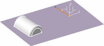
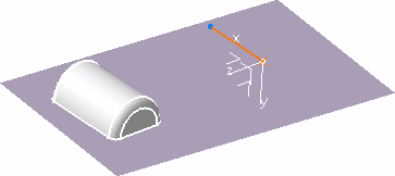
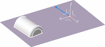
- The display mode of the axes is different depending on whether the three-axis system
is right-handed or left-handed and current or not.
| Right-handed + Current |
Right-handed + Not current |
Left-handed + Current |
Left-handed + Not current |
Solid

|
Dashed

|
Dotted

|
Dot-dashed

|
Edit an Axis System
-
Double-click the Axis System.1 in the tree.
The Axis System Definition dialog box appears.
-
Modify the values in the dialog box.
-
Click OK.
The axis system is modified.
-
Right-click Axis System.1 in the tree and select Axis System.1 object > Isolate in the context menu.
Local axes are fixed. If you want to constrain them, you need to isolate them before
defining constraints, otherwise you would obtain over-constrained
systems.
The axis system is defined independent of the geometry.
-
Click OK.
The axis system is modified.
-
Double-click any product to back in Assembly Design context.
Note:
Editing the geometric elements selected for defining the axes or the
origin point affects the definition of the axis system accordingly.
|


