-
From the Assembly
section of the action bar, click Line
 . .
The Choose a 3D Shape dialog box appears.
-
Click Create
new in the Choose a
3DShape dialog box.
In the Choose a 3D
Shape dialog box:
- The Product box displays the name of the active product.
-
3DShapes either lists the
available 3D shapes instanced under the active product or lists the available 3D shapes
instanced under a selected product. In both cases, these 3D shapes can be modified.
- The Create
new command allows you to create a 3D shape.
- The Automatically
create new 3D Shape when none exists option allows you to create a 3D
shape either under the active or selected product automatically. In this case, the
Choose a 3D Shape dialog box does not appear.
The New Content tab appears.
-
Click 3D Shape under Physical Product
Structure node in the New Content
tab.
-
Click OK in the 3D Shape dialog box.
- The new 3D Shape is created under the active product.
-
The Line Definition dialog box appears.
-
Select
 Point-Point.
- Select two points.
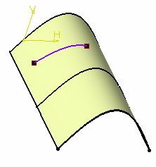
A line is displayed between the two points.
Proposed Start and
End points of the new line are shown. 
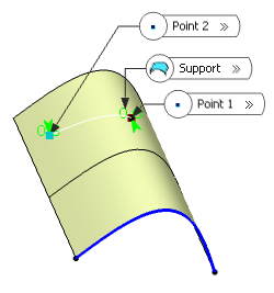
- Optional: In the Support box, select a support surface.
In this case a geodesic line is created, i.e. going from one point to the
other according to the shortest distance along the surface geometry (blue
line in the illustration below). If no surface is selected, the line is
created between the two points based on the shortest distance.

-
In the Point 1 and Point 2 boxes,
select the start and end points of the new line, that is, the line endpoint
location in relation to the points initially selected.
These points are necessarily beyond the selected
points, meaning the line cannot be shorter than the distance between the initial
points.
-
Select the Mirrored extent check box to create a line
symmetrically in relation to the selected Point 1 and
Point 2 points.
- Click OK to create
the line.
The line (identified as Line.xxx) is added to the specification
tree.
|
 .
The Choose a 3D Shape dialog box appears.
 Point-Point.

