-
From the Assembly
section of the action bar, click Line
 . .
The Choose a 3D Shape dialog box appears.
-
Click Create
new in the Choose a
3DShape dialog box.
In the Choose a 3D
Shape dialog box:
- The Product box displays the name of the active product.
-
3DShapes either lists the
available 3D shapes instanced under the active product or lists the available 3D shapes
instanced under a selected product. In both cases, these 3D shapes can be modified.
- The Create
new command allows you to create a 3D shape.
- The Automatically
create new 3D Shape when none exists option allows you to create a 3D
shape either under the active or selected product automatically. In this case, the
Choose a 3D Shape dialog box does not appear.
The New Content tab appears.
-
Click 3D Shape under Physical Product
Structure node in the New Content
tab.
-
Click OK in the 3D Shape dialog box.
- The new 3D Shape is created under the active product.
-
The Line Definition dialog box appears.
-
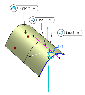
Select
 Bisecting.
- Select two lines. Their bisecting line is the line
splitting in two equals parts the angle between these two lines.
- Select a point as the starting point for the line. By
default it is the intersection of the bisecting line and the first
selected line.
-
Select the support surface.
-
Specify the line's length by defining Line End and
Point Offset values.
The corresponding bisecting line is displayed.
-
You can choose between two solutions, using Next
Solution
 , or directly clicking the numbered arrows in the
geometry. , or directly clicking the numbered arrows in the
geometry.
- Click OK to create
the line.
The line (identified as Line.xxx) is added to the specification
tree.
|
 .
The Choose a 3D Shape dialog box appears.
 Bisecting.
 , or directly clicking the numbered arrows in the
geometry.

 (not available with the point-point
line type).