Creating a Line Normal to a Curve

You can create a line at an angle to a curve that passes through a point.


Before you begin: Insert in an assembly an existing 3D shape containing geometric elements.
  1. From the Assembly section of the action bar, click Line .
    The Choose a 3D Shape dialog box appears.
  2. Click Create new in the Choose a 3DShape dialog box.

    In the Choose a 3D Shape dialog box:

    • The Product box displays the name of the active product.
    • 3DShapes either lists the available 3D shapes instanced under the active product or lists the available 3D shapes instanced under a selected product. In both cases, these 3D shapes can be modified.
    • The Create new command allows you to create a 3D shape.
      Important: When you create a new 3D shape in Assembly commands context, its Nature is set as Specification whatever your choice in the dialog box, and you cannot change the nature of this 3D shape after it has been created with this command. See Nature of a New 3D Shape Created in Assembly Commands Context.
    • The Automatically create new 3D Shape when none exists option allows you to create a 3D shape either under the active or selected product automatically. In this case, the Choose a 3D Shape dialog box does not appear.

    The New Content tab appears.
  3. Click 3D Shape under Physical Product Structure node in the New Content tab.
  4. Click OK in the 3D Shape dialog box.
    • The new 3D Shape is created under the active product.
    • The Line Definition dialog box appears.
  • Important: You switch from Assembly Design app to the last representation app you used.
    1. Select Angle/Normal to curve.
      Important:

      Repeat object after OK option has no effect in Assembly Design context.

    2. In the Curve box, select a reference curve.
    3. In the Support box, select a surface containing that curve.
      Important:
      • If the selected curve is planar, then the Support is set to Default (Plane).
      • If an explicit Support has been defined, a context menu is available to clear the selection.
      Tip: We advise you to avoid the creation of lines when the direction does not lie on the support, as well as the editing of the angle between the direction and the support in such cases.
    4. In the Point box, select a point on the curve.
    5. In the Angle box, type the value or use the arrows to change the angle value.


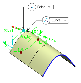
      A line is displayed at the given angle with respect to the tangent to the reference curve at the selected point. These elements are displayed in the plane tangent to the surface at the selected point.

      You can click on the Normal to Curve button to specify an angle of 90 degrees.

      Proposed Line End and Point Offset points of the line are shown.

    6. In the Line End and Point Offset boxes, select the start and end points of the new line.
      The corresponding line is displayed.
    7. Click OK to create the line.
      The line (identified as Line.xxx) is added to the specification tree.
      Important: You come back in the Assembly Design app.