Creating a Line Normal to a Surface | |||
| |||

| Important: You switch from Assembly Design app to the last representation app you used. |
-
Select
 Normal to surface.
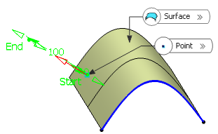
- Select a reference Surface and a Point.A vector normal to the surface is displayed at the reference point. Proposed Line End and Point Offset points of the new line are shown.
If the point does not lie on the support surface, the minimum distance between the point and the surface is computed, and the vector normal to the surface is computed at the resulting reference point and displayed at the selected point.