Creating a Mean Plane Through Points

You can create a plane defined as the mean through three or more points.


Before you begin: You must create or include a 3D Shape containing geometry.
  1. From the Assembly section of the action bar, click Plane .
    The Choose a 3D Shape dialog box appears.
  2. Click Create new in the Choose a 3DShape dialog box.

    In the Choose a 3D Shape dialog box:

    • The Product box displays the name of the active product.
    • 3DShapes either lists the available 3D shapes instanced under the active product or lists the available 3D shapes instanced under a selected product. In both cases, these 3D shapes can be modified.
    • The Create new command allows you to create a 3D shape.
      Important: When you create a new 3D shape in Assembly commands context, its Nature is set as Specification whatever your choice in the dialog box, and you cannot change the nature of this 3D shape after it has been created with this command. See Nature of a New 3D Shape Created in Assembly Commands Context.
    • The Automatically create new 3D Shape when none exists option allows you to create a 3D shape either under the active or selected product automatically. In this case, the Choose a 3D Shape dialog box does not appear.

    The New Content tab appears.
  3. Click 3D Shape under Physical Product Structure node in the New Content tab.
  4. Click OK in the 3D Shape dialog box.
    The new 3D Shape is created under the active product.
  5. Click OK in the 3D Shape dialog box.
    • The new 3D Shape is created under the active product.
    • The Axis System Definition dialog box appears. The axis system's parameters Origin, X axis, Y axis, and Z axis are automatically computed, and Default (Computed) appears in the boxes.
  • Important: You switch from Assembly Design app to the last representation app you used.
    1. Select Mean through points.
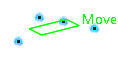
    2. Select three or more points to display the mean plane through these points.


      The command first computes a center of gravity and then the inertia matrix at this new point. In the next step, eigenvalues and eigenvectors of this matrix are computed. The eigenvectors describe the basis of the mean axis of the affine sub-space, generated by the set of input points.

      Thus, the returned origin is the center of gravity and the returned vectors are the eigenvectors of the inertia matrix from which a mean plane is computed.

      Tip: You can edit the plane by first selecting a point in the dialog box list and choose one of the following options:
      • Remove the selected point
      • Replace the selected point by another point.
    3. Click OK to create the plane.
      The plane (identified as Plane.xxx) is added to the tree.
      Important: You come back in the Assembly Design app.