Creating a Plane Normal to another Plane

You can create a plane at an angle to a reference plane based on a rotation axis.


Before you begin: You must create or include a 3D Shape containing geometry.
  1. From the Assembly section of the action bar, click Plane .
    The Choose a 3D Shape dialog box appears.
  2. Click Create new in the Choose a 3DShape dialog box.

    In the Choose a 3D Shape dialog box:

    • The Product box displays the name of the active product.
    • 3DShapes either lists the available 3D shapes instanced under the active product or lists the available 3D shapes instanced under a selected product. In both cases, these 3D shapes can be modified.
    • The Create new command allows you to create a 3D shape.
      Important: When you create a new 3D shape in Assembly commands context, its Nature is set as Specification whatever your choice in the dialog box, and you cannot change the nature of this 3D shape after it has been created with this command. See Nature of a New 3D Shape Created in Assembly Commands Context.
    • The Automatically create new 3D Shape when none exists option allows you to create a 3D shape either under the active or selected product automatically. In this case, the Choose a 3D Shape dialog box does not appear.

    The New Content tab appears.
  3. Click 3D Shape under Physical Product Structure node in the New Content tab.
  4. Click OK in the 3D Shape dialog box.
    The new 3D Shape is created under the active product.
  5. Click OK in the 3D Shape dialog box.
    • The new 3D Shape is created under the active product.
    • The Axis System Definition dialog box appears. The axis system's parameters Origin, X axis, Y axis, and Z axis are automatically computed, and Default (Computed) appears in the boxes.
  • Important: You switch from Assembly Design app to the last representation app you used.
    1. Select Angle/Normal to plane.
      Important:

      Repeat object after OK option has no effect in Assembly Design context.

    2. In the Reference box, select a plane.
    3. In the Rotation axis box, select an axis or a line.
      This axis can be any line or an implicit element, e. g. a cylinder axis. To select the latter press and hold the Shift key while moving the pointer over the element, then click it.
    4. Specify the angle by changing the value in the Angle box or by manipulating the handle in the work area.


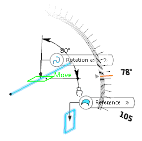
      The plane is created at the mid point of the rotation axis with the specified angle to the reference plane.

    5. Click Normal to plane to set the angle value to 90deg.
    6. Select Project rotation axis on reference plane .
      The plane will be created on the rotation axis projected into the reference plane.

      If the rotation axis is not parallel to the reference plane, it is aligned to be parallel and the plane will be created on the aligned rotation axis.


    7. Click OK to create the plane.
      The plane (identified as Plane.xxx) is added to the tree.
      Important: You come back in the Assembly Design app.