-
From the Assembly
section of the action bar, click Point
 . .
The Choose a 3D Shape dialog box appears.
-
Click Create
new in the Choose a
3DShape dialog box.
In the Choose a 3D
Shape dialog box:
- The Product box displays the name of the active product.
-
3DShapes either lists the
available 3D shapes instanced under the active product or lists the available 3D shapes
instanced under a selected product. In both cases, these 3D shapes can be modified.
- The Create
new command allows you to create a 3D shape.
- The Automatically
create new 3D Shape when none exists option allows you to create a 3D
shape either under the active or selected product automatically. In this case, the
Choose a 3D Shape dialog box does not appear.
The New Content tab appears.
-
Click 3D Shape under Physical Product
Structure node in the New Content
tab.
-
Click OK in the 3D Shape dialog box.
The new 3D Shape is created under the active product.
-
Click OK in the 3D Shape dialog box.
- The new 3D Shape is created under the active product.
- The Axis System Definition
dialog box appears. The axis system's parameters Origin,
X axis, Y axis, and Z
axis are automatically computed, and Default
(Computed) appears in the boxes.
-
Select
 On plane.
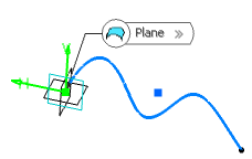
-
In the Plane box, select a plane.
If you select one of the planes of any local axis system as the plane, the origin
of this axis system is set as the reference point and featurized. If you modify
the origin of the axis system, the reference point is modified accordingly.
-
Optional: Select a point to define a reference for
computing coordinates in the plane.
If no point is selected, the projection of the model's
origin on the plane is taken as a reference.
-
Optional: Select a surface on which the point is projected normally
to the plane.
H and V are computed from the directions belonging to the geometrical plane. If
the plane is moved, during an update for example, the reference direction
would then be projected on the plane.
-
Click in the plane to display a point.
-
Click OK to create the point.
The point (identified as Point.xxx) is added to the
tree.
|