Method 1
This topic provides information about the methods 1.
The type of modifications performed depends on the position of the joggle with regards to:
- the end of the part:
- near the end of part (case 1)
- not near the end of part (case 2)
- the position of other joggles:
- twin joggles (case 3)
- double joggle near the end of part (case 4)
- double joggle not near the end of part (case 5)
How the different cases and the deformation are managed
This sub-topic provides information about the way the different cases and the deformation are managed.
Six values are used in the following description: C1, C2, C3, C4, C5, Ra. These values are defined in a design table. The path to this design table is defined in the Std_Method1.xls file.
Here is an example of a design table:
| JoggleCompensation_C1 | JoggleCompensation_C2 | JoggleCompensation_C3 | [...] |
|---|---|---|---|
| 75 | 5 | 150 | [...] |
[table continued below]
| [...] | JoggleCompensation_C4 | JoggleCompensation_C5 | JoggleCompensation_Ra |
|---|---|---|---|
| [...] | 10 | 75 | 3 |
Case 1

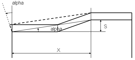
The parameters necessary for performing the modifications are as follows:
- The parameter of the feature is: S (joggle depth)
- Some values are computed to define the type of deformation: alpha, X.
The parameter definition and links are as follows:
- This case is applied if X < C1.
- C1 is defined with a constant value.
This deformation is performed as follows:
- The alpha angle is computed from S and X ( tangent(alpha) = S / X ).
- The side and the EOP are then rotated with the alpha angle. The center of rotation is the intersection between the BTL on the flange and the side.
Case 2

The parameters necessary for performing the modifications are as follows:
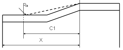
The values of the modification are: C1, Ra.
The parameter definition and links are as follows:
- This case is applied if X > C1.
- C1 is defined with a constant value.
- Ra is defined with a constant value.
Case 3

The parameters necessary for performing the modifications are as follows:
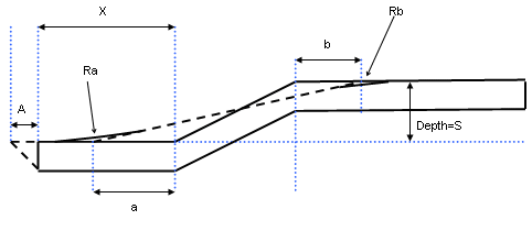
- The values of the modification are: C2, C3, C4, Ra.
- A value is computed to define the type of deformation (table) to apply: X.
The parameter definition and links are as follows:
- This case is applied if C3 > X > C2.
- Then: a = (X - C4) / 2.
- C2, C3 and C4 are defined with a constant value.
- Ra is defined with a constant value.
Case 4
This case applies only to the joggle positioned on the right; the joggle positioned on the left follows case 1.

The parameters necessary for performing the modifications are as
follows:
A value is computed to define the type of deformation (table) to apply: X.
The parameter definition and links are as follows:
- This case is applied if C4 > X.
- C4 is defined with a constant value.
Case 5
This case applies only to the joggle positioned on the right; the joggle positioned on the left follows case 2.

The parameters necessary for performing the modifications are as
follows:
A value is computed to define the type of deformation (table) to apply: X.
The parameter definition and links are as follows:
- This case is applied if C5 > X.
- C5 is defined with a constant value.
