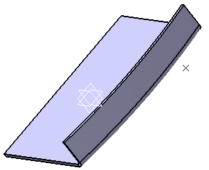
- Select the point and then click Point or Curve Mapping
 in the Model section of the action bar. in the Model section of the action bar.Elements selected for the mapping are listed in the Unfold object definition dialog box.
- From the Type list, select one of the following options.
The type lets you specify if the element to be created is needed in the Sheet Metal process or if it is only a construction element. | Option | Description |
|---|
| Construction Element | Creates elements in an intermediary construction.
These elements do not appear in the unfolded view of the
drawing. |
|---|
| Characteristic Element | Creates elements needed in the drawing for measures. These elements appear in the
drawing if required in by the
administrator. |
|---|
| Marking and Engraving | Creates elements
making part of the laser process. These elements appear
in the drawing if required in
by the administrator. |
|---|
The curve mapping is previewed as if the surfacic flange onto which it has been drawn was unfolded.

- Click OK to create the mapping.
- From the standard area of the action bar, click Fold/Unfold
 . . - From the Refine section of the action bar, click Circular Cutout
 . .
- Select a point as the center of the hole and
the surfacic flange as the support of the hole.
- Click OK.
-
From the standard area of the action bar, click Fold/Unfold
 again. again.
|