-
From the Model
section of the action bar, click Point
 . .
-
Select
 On surface.
-
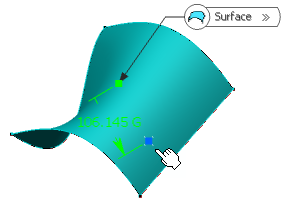
In the
Surface box, select the surface where the
point is to be created.
-
Optional: Select a reference point.
By default, the surface's middle point is taken as a reference.
-
Optional: Select an element to use its orientation as
a reference direction or a plane to take its normal as a reference direction.
You can also use the
context menu
to specify the X, Y, Z components of the reference direction.
-
In the Distance box, enter the value or use the arrows
to change the value of a distance along the reference direction to display a
point.
-
Select the dynamic positioning of the point:
- Coarse (default behavior): the distance computed between the
reference point and the pointer is a Euclidean distance. Therefore, the
created point may not be located at the location of the pointer. The
handle (symbolized by a red cross) is continually updated as you move
the pointer over the surface.

- Fine: the distance computed between the reference point and the
pointer is a geodesic distance. Therefore, the created point is located
precisely at the location of the pointer. The handle is not updated as
you move the pointer over the surface, only when you click the surface.
-
Click
OK to create the point.
The point (identified as Point.xxx) is added to the
tree.
Note:
- The dynamic positioning option is persistent but is not stored in the feature. Therefore, while editing,
the dynamic positioning may not be the one you selected.
|
 .
.
 On surface.
