About Robot Manipulations in Assembly Experience

This section describes how to use the Robot manipulation handles for moving track objects by translation, planar, or rotation.

This page discusses:

Robot Manipulation Handles

The Robot manipulation handles are used in Assembly Experience for track creation.

Depending on the selected Robot manipulation handle, the selected object can move in a translation direction, a planar direction or according to a rotation.

The translation manipulation handle is as follows:
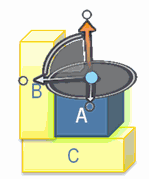


The selected part is highlighted in green. The Robot manipulation handle in the extraction direction is active.

The planar manipulation handle is as follows:
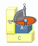


You select the planar Robot manipulation handle to switch to planar motion.

The rotation manipulation handle is as follows:
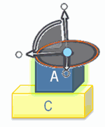


You select the rotation Robot manipulation handle to switch to rotation mode. By default, the rotation is centered round the picked point of selected object.

Notes:
  • You can change the Robot position by snapping it to any other geometry.
  • Selection of a manipulation handle allows changing extraction direction or manipulation mode.
  • The default Robot position is the center on the picked point of the selected object.
  • When you reselect the same product, the Robot position is not set to the picked point. The Robot is only set on the mouse position at the first product selection.
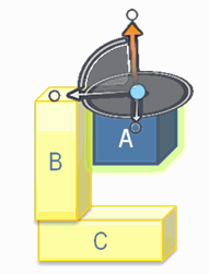
Trajectory Point Creation

You can create one or more trajectory points in a track.

A trajectory point is created when:

  • You select a new Robot manipulation handle
  • You double-click a part surface to change extraction direction
  • You end track editing.

When you move the part according to a direction, release the left mouse button, and continue manipulation in the same direction. There is no point trajectory added when you release the left mouse button.

Track Creation with Robot Manipulation Handles

You can use the Robot manipulation handles for creating tracks.

You can create a track by:

  • Moving the selected part according to the active direction (there is no need to select the Robot manipulation handle because of extraction direction is already specified) for translation and planar motions.
  • Moving one of the Robot manipulation handles (translation/planar/rotation). In this case, the part moves according to the manipulation handle direction.

When the selected part is moving, only the active manipulation handle and the corresponding manipulation handle ruler appear.

Use of Ruler During Track Creation

A ruler can be displayed for translations, planar movements, and rotations.

During the track creation, the ruler gives:

  • An editable displacement or rotational measurement
  • Clash information (if a clash is detected during the part displacement, the ruler is displayed in red).

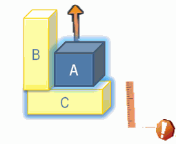
When the selected part is moved to a clash direction:

  • The ruler appears in red.
  • The part in clash appears in blue highlight.
  • The selected object stops moving.

Translation Ruler

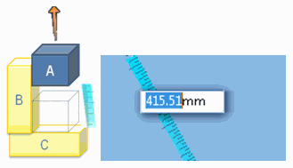
The exact value of the object translation appears in the ruler. In addition, you can edit the ruler value:


If the selected part is not in clash for this new value, the translation is applied according to the new value. If the value specified on the ruler leads to a clash, the part is not moved and a message displays.

Planar Ruler

The planar ruler is a combination of two translation rulers.

You can edit each of these two translation rulers.

If selected part is not in clash for the new values, the planar motion is applied corresponding to the new values. If the values specified on the ruler lead to a clash, the part is not moved and a message appears.

Rotation Ruler

When you apply a rotation, a ruler for rotation appears. You can edit the rotation value.

If selected part is not in clash for this new value, the rotation is applied corresponding to this new value. If the value specified on the ruler leads to a clash, the part is moved and a message appears.

Clash Information

A visual aid is provided to give clash information when creating assembly trajectories.

Case of no clash:


The selected part is highlighted in green. The Robot manipulation handle in extraction direction is active.

Case of clash for extraction direction:


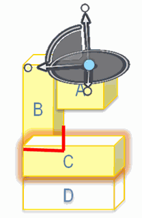
The part in clash is highlighted in red. The other parts (not in clash) are ghosted.

You can customize the display of the collision curve (in red) and the highlight on clash through options in Me > Preferences > Infrastructure > DELMIA Infrastructure > Clash.

Case of parts collision:


The parts in collision are highlighted in blue (excepted selected part). The ruler appears in red.