-
From the Steel Detailing section of the action bar, click Base Plate
 . .
The building is hidden, the catalog columns are shown as transparent,
and their neutral axes are displayed.
-
Select the neutral axis of a catalog column.
-
In the Base Plate dialog box, select the shape of the base
plate.
- To create a rectangular
base plate, perform the following steps:
- Select
Rectangle
 . .
- In the Length
U and the Length V boxes,
specify the lengths of the rectangle in the U and V directions.
- In the
Rotation box, specify an angle to rotate
the rectangle about its center in the same positioning plane.
- In the Chamfer
length box, specify the chamfer length. Select the
check boxes corresponding to the plate's corners that you want to
chamfer.
- In the
Thickness box, specify the thickness of
the plate.
- Select the Cut host member check box to cut
the end of the column at which the base plate is positioned.
Note:
You can click  to swap the values of the Length U and Length V of the
rectangle. to swap the values of the Length U and Length V of the
rectangle.
- To create a square base
plate, perform the following steps:
- Select
Square
 . .
- In the
Length box, specify the length of the
side of the square.
- In the
Rotation box, specify an angle to rotate
the square about its center in the same positioning plane.
- In the Chamfer
length box, specify the chamfer length. Select the
check boxes corresponding to the plate's corners that you want to
chamfer.
- In the
Thickness box, specify the thickness of
the plate.
- Select the Cut host member check box to cut
the end of the column at which the base plate is positioned.
- To create a round plate,
perform the following steps:
- Select
Round
 . .
- In the
Diameter box, specify the diameter of the
plate.
- In the
Thickness box, specify the thickness of
the plate.
- Select the Cut host member check box to cut
the end of the column at which the base plate is positioned.
- To create a plate of any
other shape, perform the following steps:
- Select
Profile
 . .
- Select a closed profile.
- In the
Rotation box, specify an angle to rotate
the profile about its center in the same positioning plane.
- In the
Thickness box, specify the thickness of
the plate.
- Select the Cut host member check box to cut
the end of the column at which the base plate is positioned.
-
To position the origin of the U, V axes of the base plate relative to the host
column, select any one alignment point.
Note:
The alignment points that can be selected are displayed at the
bottom of the catalog column.
-
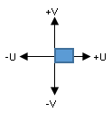
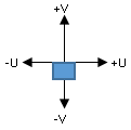
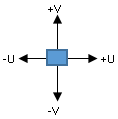
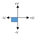
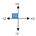
Align the plate in the U and V directions.
| Orientation |
V minus
 |
V center
 |
V plus
 |
U plus
 |
 |
 |
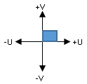 |
U center

|
 |
 |
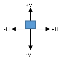 |
U minus
 |
 |
 |
 |
-
Select the thickness orientation of the plate.
| Option | Description |
|---|
Up |
Applies the thickness in the upward direction, normal to the UV
plane. |
Down |
Applies the thickness in the downward direction, normal to the UV
plane. |
Both |
Applies the thickness centered on the the UV plane. |
-
Click Base Plate Options
 and specify the offsets for the plate in the U, V, and W directions.
Notes:
- You can click
 to reset the offset values to zero. to reset the offset values to zero.
- You can select the
Show additional alignment points check
box to display the additional alignment points that can be selected.
-
Click Ok
 . .
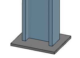
The base plate is created.
|