-
From the Steel Detailing section of the action bar, click Member-Driven
Plate
 . .
The building is hidden, the catalog members are shown as transparent,
and their neutral axes are displayed. Pickable segments of plates and of clip
angles are also displayed.
-
Select a positioning point on the neutral axis of a catalog member, a plate,
or a clip angle.
-
In the Member-Driven Plate dialog box, select the shape
of the plate.
- To create a rectangular
plate, perform the following steps:
- Click Rectangle
 . .
- In the Length
U and Length V boxes, specify
the lengths of the rectangle in the U and V directions.
- In the
Rotation box, specify an angle to rotate
the rectangle about its center in the same positioning plane.
- In the Chamfer
length box, specify the chamfer length. Select the
check boxes corresponding to the plate's corners that you want to
chamfer.
- In the
Thickness box, specify the thickness of
the plate.
Note:
You can click  to swap the values of the Length U and the
Length V of the rectangular plate.
to swap the values of the Length U and the
Length V of the rectangular plate.
- To create a square plate,
perform the following steps:
- Click
Square
 . .
- In the
Length box, specify the length of side of
the square.
- In the
Rotation box, specify an angle to rotate
the square about its center in the same positioning plane.
- In the Chamfer
length box, specify the chamfer length. Select the
check boxes corresponding to the plate's corners that you want to
chamfer.
- In the
Thickness box, specify the thickness of
the plate.
- To create a triangular
plate, perform the following steps:
- Select
Triangle
 . .
- To rotate the triangle by 90 degrees about its normal, click
Snap Rotate About Normal
 . .
- To flip the normal of the UV plane, click
Reverse
 . .
- In the Length
U and Length V boxes, specify
the lengths of the triangle in U and V directions.
- In the
Rotation box, specify an angle to rotate
the triangle about its center in the same positioning plane.
- In the Chamfer
length box, specify the chamfer length. Select the
Chamfer -U,-V check box to chamfer the
right-angled corner of the triangle.
- In the
Thickness box, specify the thickness of
the plate.
Note:
You can click
to swap the values of the Length U and the
Length V of the triangular plate.
- To create a round plate,
perform the following steps:
- Select
Round
 . .
- In the
Diameter box, specify the diameter of the
plate.
- In the
Thickness box, specify the thickness of
the plate.
- To create a plate of any
other shape, perform the following steps:
- Select
Profile
 . .
- Select a closed profile.
- To rotate the closed profile by 90 degrees about profile’s normal,
click Snap Rotate About Normal
.
- To flip the normal of the UV plane, click
Reverse
.
- In the
Rotation box, specify an angle to rotate
the profile about its center in the same positioning plane.
- In the
Thickness box, specify the thickness of
the plate.
Note:
When you position a member driven plate on a round
host member, a Revolve box appears. This parameter
specifies the angle by which the plate is revolved around the neutral axis
of the host member.
-
To position the origin of the U, V axes of the plate relative to the host
column, select any one alignment point.
Note:
The alignment points that can be selected are displayed in the
work area.
-
Click Snap Rotation To Next Plane
 to change the orientation of the plate and link it to another plane relative to
the host member.
to change the orientation of the plate and link it to another plane relative to
the host member.
-
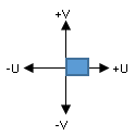
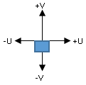
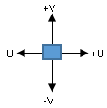
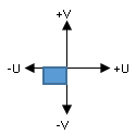
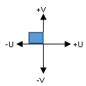
Align the plate in the U and V directions.
| Orientation |
V minus
 |
V center
 |
V plus
 |
U plus
 |
 |
 |
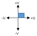 |
U center

|
 |
 |
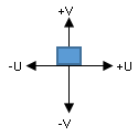 |
U minus
 |
 |
 |
 |
-
Select the thickness orientation of the plate.
| Option | Description |
|---|
Front side
 |
Applies the thickness on the positive side of the UV plane.
|
Back side
 |
Applies the thickness on the negative side of the UV plane. |
Both sides
 |
Applies the thickness centered on the UV plane. |
-
Click Member-Driven Plate Options
 and specify the offsets for the plate in the U, V, and W directions. and specify the offsets for the plate in the U, V, and W directions.
Notes:
- You can click
 to reset the offset values. to reset the offset values.
- You can select the Show additional
alignment points check box to display the additional
alignment points that can be selected.
-
Click Ok
 . .
The member-driven plate is created. 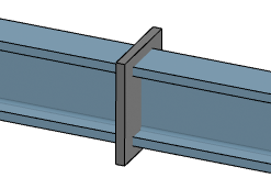
|