Creating a Reference Plane Grid | ||
| ||
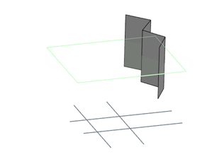
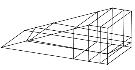
Context: When creating a structural grid from a solid or surface body, the grid includes:
- The edges of the solid or surface body.
- The edges formed by the intersection on the faces of the solid or surface body and the planes formed by the extrusions of sketch lines.
When creating a structural grid from axis systems, the grid is displayed on the YZ plane of the selected axis system.
-
Before you begin, choose one of the following:
- Create the reference plane and sketch, that is:
- From the Wireframe and Surface section of the action bar, use Plane
 or
Axis System
or
Axis System
 to create a few
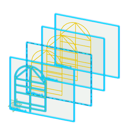
planes or axis systems. For example, you can create four planes offset from the
Front plane.
to create a few
planes or axis systems. For example, you can create four planes offset from the
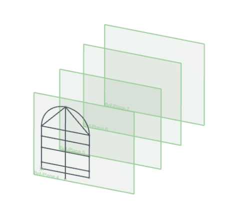
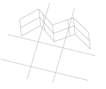
Front plane.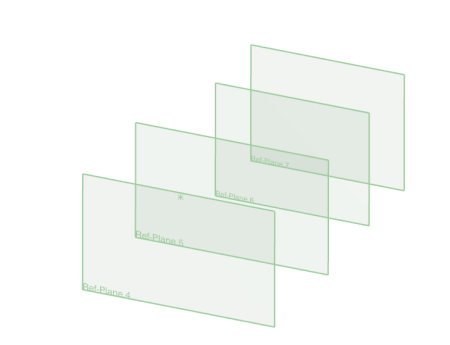 Note: Your reference planes or the YZ planes of your axis systems need not be parallel to the sketch plane or to each other.
 - Sketch the grid that is to serve as the basis for the reference plane grid.
- From the Wireframe and Surface section of the action bar, use Plane
- Create a solid body.
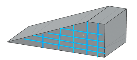 Note: Optionally, you can sketch gridlines on part of the solid body.
 - Create a surface body.
 Note: Optionally, you can include gridlines and reference planes.
- Create the reference plane and sketch, that is:
-
From the
Building section, click Reference Plane Grid
 .
.
-
Select the sketch for the basis of the reference plane grid as follows:
- In the Reference Planes Grid dialog box, click Select Profile
 .
. - From the 3D area, click the sketch or lines that are to serve as the basis for the reference plane grid.
- In the Reference Planes Grid dialog box, click Select Profile
- Select the reference planes as follows:
- In the dialog box, click Select Reference Plane.
-
In the tree, click each reference plane or each axis system on
which you want the reference plane grid to display.
In the 3D area, a preview of the reference plane grid on each selected reference plane is displayed. If you select an axis system, a preview of the reference plane grid on the YZ plane of each selected axis system is displayed.
-
Click
 .
.
The reference plane grid appears on all the selected reference
planes. 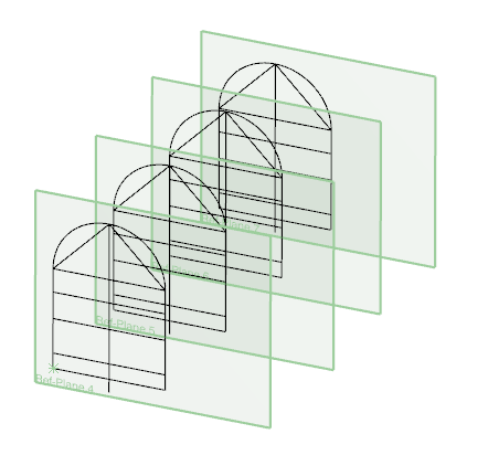
In
the tree, the system displays Reference Plane
Grid in Shell and Core in the Structure
Grids node.