Work Area | ||||||
|
| |||||
Trimetric Planes

You
can use the Trimetric planes XY, YZ,
and ZX for model orientation. The blue arrows indicate the
default coordinate axes; + X-axis, + Y-axis, and + Z-axis.
Reference Triad
Helps orient you when viewing products in the work area. 
Use the triad in the upper right corner of the work area to pick a plane for viewing a model. When you
hover over a side of the triad, the triad face is shaded. Click the highlighted
triad face and the triad and the model becomes normal to the selected plane. When
you click the same face successively, the view flips 180 degrees. Click any axis in
the triad and the component in the work area becomes normal to that axis.

Click the arrow next to the triad to open a context toolbar with additional tools. Depending on your app,
context toolbar options vary. 
- Click Translucency Manager
 to display the translucency slider. Drag the translucency slider to apply
translucency to the selected part or face.
 - Click Normal To
 to display a model from the selected plane.
 - Click View Selector
 to open the View Selector tool.
 - Click Reframe
 to recenter the view on the active model.
 - Click Trimetric View
 to apply a standard trimetric view.
 - Click Toggle Triad Model
 to change the triad model between a chair, camera, and removing the triad
model.
 - Click Pin View Bar
 to pin the view bar to the graphics area. Click
  to unpin
the view bar from the graphics area.
 - Exit Isolate
 appears next to the triad when a component has been isolated using the
Isolate
 command in the context toolbar. Click Exit Isolate to exit the
Isolate command.
 - Exit Translucency
 appears next to the triad when a component has been selected for
translucency using the Translucency Manager
 command in the context toolbar. You can specify the level of translucency from the translucency slider.
Click Exit Translucency to exit the command.
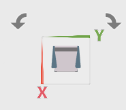
Rotating Model Clockwise and Counter-Clockwise
When the triad is in an orthogonal view, a set of controls appear around the triad to enable
spinning the model 90 degrees clockwise or counter-clockwise.
- Click Spin Clockwise
 to spin the model 90 degrees clockwise.
 - Click Spin Counterclockwise
 to spin the model 90 degrees counter-clockwise.
Exit Button Stacking
If you have more than one active command running, the exit buttons stack in a menu at the
triad.
If one command is active, that exit button is displayed. If multiple commands are active, one exit button displays with a menu. Click the triangle to display the other active commands.

If the command shown at the top of the menu list is exited, the next active command
moves up the menu list. When all of the active commands are exited, no exit buttons
appear.
Reference Geometry
To hide or show the reference geometry in the Design Manager, click Top
 , Front
  , or Right
  and select Hide
![]() from the context toolbar. Click View Filter
from the context toolbar. Click View Filter
![]() to hide or show all the
reference planes with one click.
to hide or show all the
reference planes with one click.
Callouts and Handles
Callouts, which appear in the work area when you select certain tools, let you change
values directly in the work area. Handles let you dynamically move and change
certain parameters within the work area. For more information
about the Robot and handles, see About the Robot. 
