Allocating a Lattice Area

You can allocate an area inside a part for lattice creation. You can use various Part Design and Generative Shape Design features to specify the lattice area.

Note: Using the Cavity option, you can also create lattice area for a combination of open and closed cavities.

This task shows you how to:

Allocate a Closed Lattice Area

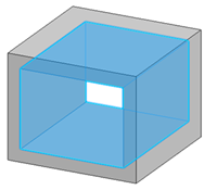
You can allocate an area inside a part containing one or more closed areas.

Before you begin: Create a part containing one or more closed areas.
  1. From the Design Lattice Area section of the action bar, click Lattice Area .
  2. In the Lattice Area.x dialog box, select the required cell type in the Cell type list. The following default cell types are available in the list:
    • BccCubic
    • BccFcc
    • Crown
    • Cube
    • Diamond
    • Dode
    • Fcc
    • Honeycomb

    Note: The Administrator can edit or customize the default standards. For more information, see Administration.

  3. In the Length and Radius boxes, specify the required values.
  4. In the Position box, select an axis system, to define the initial cell position for all the selected cavities.

    • You can right-click the Position box and select Insert Wireframe > Create Axis System to create a new axis system for positioning the lattice area.
    • If an axis system is not manually selected, the default axis system is used for the cell positioning.

  5. Under Area Selection, select the area type as Cavity.

  6. Select the required areas, select a Generative Shape Design feature defining a closed area, or click to select all the highlighted closed areas.

    Notes:
    • You can select cavities only from one body.
    • You can also select a combination of closed and open cavities.

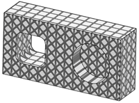
The lattice texture is displayed.

Allocate an Open Lattice Area

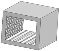
You can allocate an area inside a part containing one or more open areas.

Before you begin: Create a part containing one or more open areas, Generative Shape Design features defining open areas, or a volume connecting two solids.
  1. From the Design Lattice Area section of the action bar, click Lattice Area .
  2. In the Lattice Area.x dialog box, select the required cell type in the Cell type list. The following default cell types are available in the list:
    • BccCubic
    • BccFcc
    • Crown
    • Cube
    • Diamond
    • Dode
    • Fcc
    • Honeycomb

    Note: The Administrator can edit or customize the default standards. For more information, see Administration.

  3. In the Length and Radius boxes, specify the required values.
  4. In the Position box, select an axis system, to define the initial cell position for all the selected cavities.

    • You can right-click the Position box and select Insert Wireframe > Create Axis System to create a new axis system for positioning the lattice area.
    • If an axis system is not manually selected, the default axis system is used for the cell positioning.

  5. Under Area Selection, select the area type as Cavity.
  6. Select any one face each of the required open areas.

    Notes:
    • You can also select the following features:
      • A Generative Shape Design feature defining open areas
      • A volume connecting two solids
    • You can select cavities only from one body.
    • You can also select a combination of closed and open cavities.

  7. Optional: Select the Auto complete close check box to close the open cavity.

    Note: You can clear this option and select Generative Shape Design features to manually close the open cavities.

  8. Optional: Select the Manage Depowdering Holes check box only if the part contains de-powdering holes.

The lattice texture is displayed.
Allocate an Area for a Lattice Only Feature

You can allocate an area to generate lattices without the part.

  1. From the Design Lattice Area section of the action bar, click Lattice Area .
  2. In the Lattice Area.x dialog box, select the required cell type in the Cell type list. The following default cell types are available in the list:
    • BccCubic
    • BccFcc
    • Crown
    • Cube
    • Diamond
    • Dode
    • Fcc
    • Honeycomb

    Note: The Administrator can edit or customize the default standards. For more information, see Administration.

  3. In the Length and Radius boxes, specify the required values.
  4. In the Position box, select an axis system, to define the initial cell position for all the selected cavities.

    • You can right-click the Position box and select Insert Wireframe > Create Axis System to create a new axis system for positioning the lattice area.
    • If an axis system is not manually selected, the default axis system is used for the cell positioning.

  5. Under Area selection, select area type as Whole Shape.
  6. In the Area box, select all the faces of a shape in the 3D area or select an external Generative Shape Design feature defining the whole shape, or click to select the whole part.