Creating a Shell | |||
| |||
-
From the Design Lattice
Area section of the action bar, click
Shell
 .
The Shell.xdialog box appears.
 -
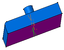
Select the face to be removed.
The selected face becomes purple
 .
.

Tip: You can click  in
the Faces to
remove box to see the list of selected elements and manage
them.
 - In the Inside thickness and the Outside thickness boxes, enter the required values.
-
In the
Other faces box, select the other faces to be
thickened with different thickness values.
The selected face becomes brown
 .
. -
In the Other thicknesses box, click
 and in
the table that appears, do the following:
- In the Inside thickness and the Outside thickness columns, enter the required values.
- Repeat the step a for other faces.
-
Optional: In the table, click
 next to the element to remove it from the list.
The table displaying other faces and the respective thickness values is updated. -
Click
 to
propagate the specified thickness to the faces tangent to the selected
faces.
Notes:
to
propagate the specified thickness to the faces tangent to the selected
faces.
Notes:- This option is separately available for the Faces to remove and Other thicknesses faces.
- If a face is tangent to a face to remove and an other thickness face, then the face is considered as a face to be removed.
-
Select the
Smoothing from the following types:
-
None: No smoothing is applied. This is the default option. The Max deviation box is unavailable.
-
Manual: Smoothing is applied as per the maximum deviation. The default value is 0.1 mm.
-
Automatic: Smoothing is applied automatically.
-
- Optional: Select one of the Regularization types on the offset surface:
- Local: regularizes the offset surface locally to minimize the deviation.
This option improves the number of successful computations by adding local adaptations to the offset body. As a result, new internal faces, edges or vertices may be created. However, as the distortion is local, deviation area is restrained and the deviation is lower.
- Global: regularizes the offset surface completely. If the local regularization fails, an informative prompt is displayed and the offset surface is globally regularized.
Important: The Regularization option is available only with the Automatic and Manual smoothing modes. - Local: regularizes the offset surface locally to minimize the deviation.
-
Click
OK
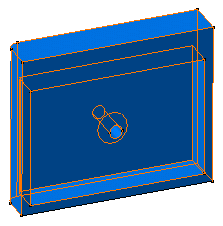
to create the shell feature.
