Creating a Connection Assembly

Positioning Components

You can position plate and hole components on the input members.

  1. In the Regular Connection Assembly or the Connection Assembly Instantiation dialog box, select a component cell, click and select Edit Position .
  2. In the Position Editor dialog box, select a positioning mode and specify the inputs as follows:
    ModeDescription
    End Plate Position Mode

    Use this positioning mode to position a component at the start or end of the member.

    • Component Location:
      • Primary: Select an input member.
      • Ratio: Position along the trace of the member. 0 = Start, 1 = End.
    • Component Axis: Specify offsets along the axes of the component. You can use the Invert Direction and Swap Directions buttons to position the component effectively.
    Profile to Profile Position Mode

    Use this positioning mode to position a component with respect to two members.

    • Component Location:
      • Primary: Select an input member.
      • Primary reference: Select a face of the member from the list.
      • Secondary: Select another input member.
      • Secondary reference: Select a face of the member from the list.
      • Angle: Specify an angle to rotate the component about z-axis of the component's axis system.
    • Component Axis: Specify offsets along the axes of the component. You can use the Invert Direction and Swap Directions buttons to position the component effectively.
    Profile to Plate Position Mode

    Use this positioning mode to position a component with respect to a member and a plate.

    • Component Location:
      • Primary: Select an input member.
      • Primary reference: Select a face of the member from the list.
      • Secondary: Select a component plate.
      • Secondary reference: Select a face of the component plate from the list.
      • Angle: Specify an angle to rotate the component about z-axis of the component's axis system.
    • Component Axis: Specify offsets along the axes of the component. You can use the Invert Direction and Swap Directions buttons to position the component effectively.
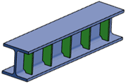
    Plate in Profile Position Mode

    Use this positioning mode to position continuity plates on a member to strengthen the member section.

    • Component Location:
      • Primary: Select an input member.
      • Primary reference: Select a face of the member from the list.
      • Ratio: Position along the trace of the member. 0 = Start, 1 = End.
    • Component Axis: Specify offsets along the axes of the component. You can use the Invert Direction and Swap Directions buttons to position the component effectively.
  3. Click OK.