Creating a Member Using Two Points | |||||
|
| ||||
-
From the Function section of the action bar,
click Member - Point to Point
 .
.
- Specify a section for the member.
Toolbar Illustration 
 : Section standard
 : Section shape
 : Section size
 : Search a section reference.
-
On the toolbar, click Section
 .
.
-
On the subsequent toolbar, click Search Section
and
select a section reference.
-
Click Section
again
and select the section size from the list.
- Select a start point and then an end point for the member.The member is created, and listed in the Member List - Point to Point dialog box.
Column Description Type The Type column specifies the type of the member, that is beam or column. The type is decided using the compatibility criteria specified in the Steel Connection PLM Modeling Definition resource. Member Displays the name of the member. Double-click the box to rename the member. Support Click  to replace the support of the member.
Tip: Keep on selecting pairs of start and end points, to create more members. The members are added to the Member List - Point to Point dialog box. - Apply a material to the member.
Toolbar Illustration 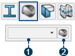
- : Material name
- : Search a material reference.
-
On the toolbar, click Material
 .
.
-
On the subsequent toolbar, click Search Material
and select a material reference.
- Define the extremities of the member.
Toolbar Illustration 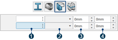
- : Start and end limiting objects
- : Limit type
- : Normal
Offset
- :
Offset
-
On the toolbar, click Extremity
 .
.
- On the subsequent toolbar, specify the start and end limits [].
You can select a plane, point, surface, or another member as a limit.
- Specify limit type, offset, and normal offset.
For more information about profile limits, see Structure Design User's Guide: Creating Members: About Members.
- Position the member.
Toolbar Illustration 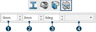
- : U offset
- : V offset
- : Angle
- : Anchor point
-
Click Position
 .
.
- Specify U offset, V offset, angle, and anchor point.
-
Click OK
 .
.
- Optional:
To edit a member, select a member in the 3D area or the
tree, and click Edit Member
 .
.
Note:
Steps 4 to 6 apply to all the members available in the Member List -
Curve dialog box.