Creating a Fluid Set | |||
| |||
-
From the Flow study section of the action bar,
click Fluid Set
 .
.
- Select the geometric elements.
- Click Join volume to join volumes that touch each other.
-
Select the type for each fluid volume:
- Fluid volume
- Pipe
To define the inner fluid for the pipe, do the following:
- Select a boundary edge or a face.
- Define the side, and select either a wet face (that is the face in contact with
the fluid) or a boundary edge.
If you select a boundary edge, you can click Other side
 to invert its
side.
- Optional:
To define a planar symmetry, select Symmetry as the
Boundary type.
You can click Invert side
 to invert the side to keep.
 When a symmetry is defined, the Fluid set information is updated in the Flow optimization assistant and shows the symmetry. Moreover, the corresponding SIMULIA symmetry feature is automatically created.
-
Click Preview to display the computed geometry.
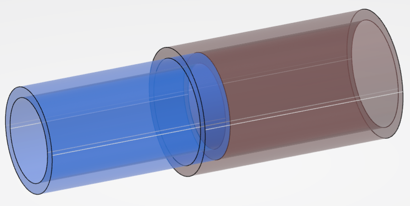
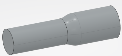
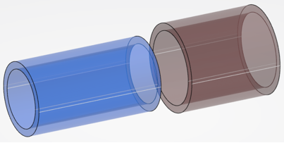
If there is a contact overlap between pipes, a smooth transition is generated between them.


-
To manage gaps between adjacent fluid elements, right-click the Elements for
fluid volumes box and select Insert volumes > Create multi-sections volume.

The feature is aggregated under the Fluid Set node in the tree. You can create as many multi-sections volumes as required. For more information, see Generative Shape Design: Creating Volumes: Creating Multi-Sections Volumes. -
In the tree, click the fluid set feature and do one of the following:
Option Description  Hide/Show
Displays hidden or shown objects alternatively. 
Show all fluid volumesShows the fluid set and all the associated fluid volumes. 
Show only this fluid setShows this disconnected feature and all its disconnected areas. 
Set transparencySets transparency to 50%.  Apply
material
Apply
materialApplies a material on this fluid set.