Applying Design Zone Specifications | |||
| |||
-
From the Surface design section of the action bar, click Apply Design Zone Specifications
 .
.
-
Choose where to apply the specifications:
- In a new geometrical set with link
- In a new geometrical set without link
- In the same geometrical set
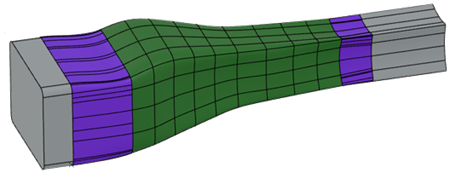
If the reconstructed surface is not connected to one inlet or outlet, a blend feature is created between the reconstructed surface and the inlet or outlet to make a smooth junction.

 :
inlet
:
inlet : reconstructed
surface
: reconstructed
surface : outlet
 : in
red, curves where junctions must be created
: in
red, curves where junctions must be createdHere is the result with the blend features shown in purple: