About Mechanical Features in Layered Product Design

A mechanical feature is an object stored inside the stacking to represent a mechanical transformation that impact several layers. There are two types of mechanical features: Some bind several layers, others cut several layers.

This page discusses:

Binding Mechanical Features

This mechanical feature binds several layers or layers groups without needing to define a material.

Possible types are

  • Cold Pressure Weld
  • Ultrasonic Weld
  • Stitching Weld
  • Other

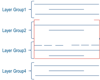
They have an area defining the application zone, and a geometry representing the pattern.

They bind all the layers (impacted layers) between a given layer up to the last layer of the group or of the stacking, or a selected layer.

The mechanical feature is stored under the given layer.

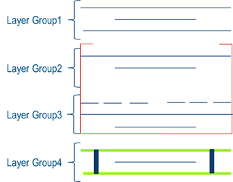
  • In the flat view (3D area), it is represented by its pattern (Sketch or sketch pattern).
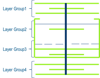
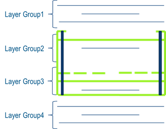
  • In elevated view (3D area), the pattern contained in the area between the bottom and the top layer is extruded.
  • In tabular view (stacking management) mechanical features are listed with the type displayed in the material column.

Cutting Mechanical Features

This mechanical feature cuts one or several layers or layers groups together, along one cutting line.

The mechanical feature cut all the selected layers (impacted layers) of the group or of the stacking. The mechanical feature is stored under a new node named Mechanical Cut Group. In the 3D area, the flat and elevated views are updated as the cut zone is removed.

Stitching Bond Features

The stitching bond feature specifies a connection between selected layers with a material.

This relation uses

  • A material with a linear density (Chord, thread).
  • Computation parameters such as net, gross, and trim length,

The stitching is a mechanical process, delimited only by its area of application, meaning it can be outside the support layer.

Computation

Mechanical features are added and positioned inside a layers group.

The layer from which the mechanical feature starts is the layer right before it in the tree (or right below in the 3D area). The geometry of the layer is projected perpendicularly on each following layer. If the projected geometry intersects even partially the layer surface, the layer is seen as impacted.

Following computation modes are proposed:

  • Up to First layer in Current Group, where projection ends at the first layer of the layers group.
    Note: Folds found inside the layers group are impacted, even though layers in between folds are from other layers groups.
  • Up to First layer in Stacking, where projection is done on all the layers of the stacking.
  • Up to selected layer, where projection ends at the selected layer.

Example of impacted layers:

  • Initial model, where the red box represents a folded layer.

  • In the images below, the mechanical feature is represented in thick solid blue, the impacted layers in thick solid green.
  • Impacted layers up to first layer in current group, starting from the bottom layer of LayerGroup4

  • Impacted layers up to first layer in stacking, starting from the bottom layer of LayerGroup4

  • Impacted layers up to first layer in current group, the group been a fold.