About Objects in Layered Product Design | ||
| ||
- The objects below are persistent in the representation of the 3D part.
- Standard activation/de-activation rules apply.
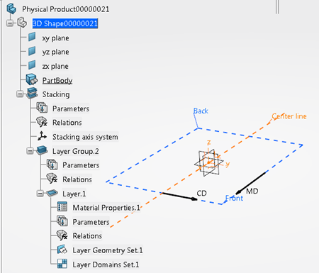
- Stacking
-
- There is only one stacking per 3D Part.
- It is the main root node that gathers all the layers.
- It contains all the layers groups (and thus the layers).
- It is based on a plane (xy plane by default)
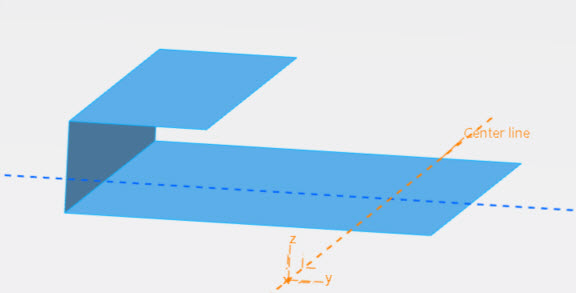
- It has a machine direction (identified as MD - positive X-axis by default) from which the cross direction is deducted (identified as CD - orthogonal to machine direction, positive Y-axis by default) and a center point (origin by default).
Once fully defined, the stacking information is displayed in the 3D area.
- Layers Group
-
- It is a structure node aggregated under the stacking.
- It provides a way to gather layers that fulfill a given function.
Once fully defined, a layers group can be used as a template to be reused in other products.
- Layer
-
- This object represents a given material laid on top of another layer.
- It is created under a layers group, not directly under a stacking.
- It can consist of several geometrical domains of material.
- A domain is based on a sketch that represents its boundary.
- A layer can be seen as a meaningful grouping in manufacturing.
Once fully defined, a layer can be used as a template to be reused in other products.
Boundaries of domain are visible in Flat view, the surface within the boundaries in Elevated view.
- Elastic Layer
- Same as Layer, with an elasticity percentage.
- Liquid Layer
- Same as Layer, only with the type LIQUID.
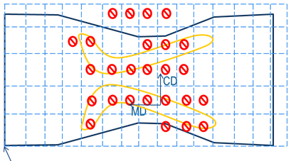
- Relation Layer
- This type of layer is used to bind two layers (the one directly above and the one
directly below) as shown in yellow below. In this example, the green lines represent
layers from LayerGroup.1, the purple lines layers from LayerGroup2.
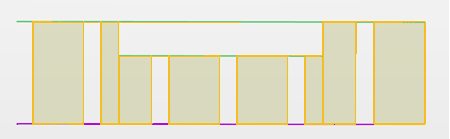 Note: Elastic and liquid layers are not taken into account. In this example, the orange layer, that is in direct contact with the relation layer, is an elastic layer. It is skipped and the relation is created with the next layer, represented by the green line.
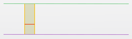
- Density Layers
- Two types of density layers are proposed: Grid Density Layer and Profile Density Layer.
They share some common behavior:
- A total weight of material to be distributed with varying thickness.
- A contour geometry that represents the boundary of the layer.Note: Density layers are mono-domain layers.
- A contour geometry representing the channels (This geometry can be multi-domain).
- Grid Density Layer
- In this layer, the quantity of material is assigned to each cell of a grid defined by
two spacings, one in the Machine Direction, one in the Cross Direction.
- Parallels are created from those spacings and a reference point (pointed by the arrow above), to entirely cover the layer and to split it into cells.
- A ratio of the total weight is assigned to each cell (The sum of all cells ratios must be 100 %).
- The cells intersecting the channels are represented by a hole.
- If the layer geometry or the channels geometry change:
- The number of parallels to create is updated, cells are deleted or created accordingly.
- Newly created cells, or cells that had a material ratio but now intersect channels or are outside the layer boundary are given a material ratio of 0.
- Cells that previously had a material ratio of 0 but no longer intersect channels or are no longer outside the layer boundary are considered as created in the Cross Direction.
- The sum of removed ratios is distributed on cells with a ratio.
- Newly created cells with a non-null ratio are given the ratio of the nearest cell with a non-null ratio, according to Cross Direction or Machine Direction, or left as is if no nearest cells are found.
- Harmonization is performed to keep the total sum of ratio equal to 100%.
Note: The last two steps are repeated until all cells have the required ratio.
- Profile Density Layer
- In this layer, the quantity of material is based on constant thickness zones and
transition zones using a 1D law (Thickness varies on Machine Direction and is constant on
Cross Direction).
The layer is split into zones, defined by planes intersecting the layer geometry. The intersecting planes are offset from the reference plane, defined by the origin point and perpendicular to the plane formed by the Machine Direction and the Cross Direction. In this example, the reference plane is shown in yellow, the intersecting planes in blue.

- Each zone is specified as constant or transition.
- A weight in kg is assigned to each zone.
- If the layer geometry changes:
- Zones are updated with the same cutting plane, and keep the same ratio.
- If one plane no longer intersects the layer geometry (thus removing a zone), the removed zone ratio is distributed to the remaining zones.
- Fold
- A layer can be folded to enclose another layer, typically an anti-leak barrier requires
several folds.
A fold is a special domain, created from a given mono-domain layer that knows on top of which layers or layers group it needs to be folded. This information is kept in the layer itself for further use in the app such as drawing to generate a folding line, model preparation for simulation, visualization in 3D viewers, etc.
Each domain is viewed as a layer.