Creating a Strain Transformation | ||
| ||
-
From the Transformation section of the action bar,
click Strain Transformation
 .
.
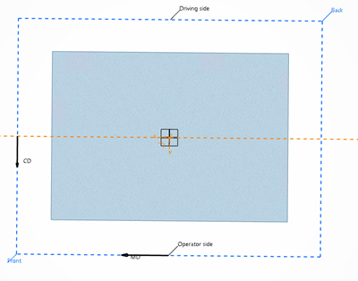
-
Select the elements to strain.
-
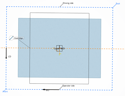
Specify Straining Zones. For each zone:
- Name the zone as required.
-
Define the Straining Element where the strain ratio is
applied.
- Either create a sketch.
For more information on working with the Sketcher, see 3D Modeling Core: Sketcher.
- Or create a symmetry.
-
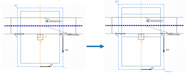
Select or draw the zones to apply the strain ratio.
-
Define the reference edge from the 3D area.
By default, it is selected in the middle of the straining zone.
-
Define the reference edge from the 3D area.
The layers are automatically strained.
![]()
The length
of layers without area, such as fold layers or elastic layers, is computed from the strain
ratio.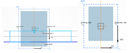
For layers with an area, such as relation layers, liquid layers, mechanical bonds,
stitching layers, the profiles are not strained. Only the spacing between profiles is
modified. ![]()
For layers with an area but no profile, the area is extended, with a warning.
The Strain Transformation feature is a structure node aggregated under a Transformation Tools node. It contains:
- The Straining Zones with their geometries.
- A Symmetrical Definition Geometry Set, if any.