Create a Module
-
From the Modules section of the action bar, click Module
 . .
-
Enter a name in the Module Definition menu and click OK.
A Module.1 (<name>) element containing a positioning axis and a geometrical set in Define In Work Object state is added to the tree.
Create two Points
-
From the Concept section of the action bar, click Point
 . .
-
In the X box, specify 30mm and click OK.
-
Create a second point in the same way with the X coordinate value 100mm.
Create a Line as Guide Curve
-
From the Concept section of the action bar, click Curve
 . .
-
Successively select Point.1 and Point.2 as start and end point of the line.
-
Click in the work area to create the line.
Create a Plane
-
From the Concept section of the action bar, click Plane
 . .
In the Plane dialog box,  Offset from Plane must be selected.
-
Select the yz-plane of the axis system.
A plane is created with the distance specified in the
Offset box. 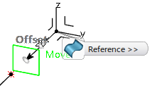 -
Select the end point of the line.
The plane is moved to the end point of the line parallel to the yz-plane. In
the Plane dialog box, the plane type changes to  Parallel through Point
. -
Click OK.
Create a Sketch as Profile Curve
Create a Concept Surface
-
From the Concept section of the action bar, click Concept Surface
 . .
-
In the Concept Surface Creation Wizard, select
 in the Scenario box. in the Scenario box.
-
Select Curve.1 as guide curve and Sketch.1 as profile.
-
Click Finish to create the concept surface.
-
Click in the work area
to exit the command.
Create and Modify an additional Section and Sketch
You can add additional sections and create sketches on them. You can modify the concept surface by reversing the profile running direction.
By default, the concept surface has two sections (Section.1 and Section.2) at its extremities.
-
In the tree, select Concept Surface.1.
Selecting Concept Surface.1 selects its components Curve.1, Sections.1, and Face Outputs.
-
In the Sections section of the Selection panel, select Section.1 -- 0 -- Sketch.1 from the Sections list.
-
Click Duplicate Section
 . .
Section.1 is duplicated and inserted as Section.3 between Section.1 and Section.2. 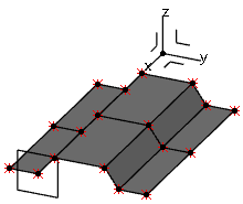 -
Select Section.3.
-
In the Sketch section of the Concept Surface Section panel, click
 . .
Sketch.2 is created.
-
Select Sketch.2 and click Edit Sketch
 in the context toolbar to load Sketch.2 in the Concept Structure Engineering Sketcher app. in the context toolbar to load Sketch.2 in the Concept Structure Engineering Sketcher app.
-
On Line.3 of the Sketch, double-click ID: 3.
-
In the Modify Domain ID dialog box, click Reverse, and then click OK.
The profile running direction is reversed. 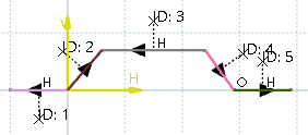 -
Click
 to exit the Concept Structure Engineering Sketcher app. to exit the Concept Structure Engineering Sketcher app.
The result shows the impact of the direction on the surface shape. 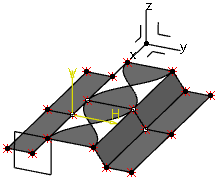
Modify the Concept Surface
You can delete parts of the concept surface and modify its shape.
-
Restore the original direction of the Line.3 with ID: 3 as described.
-
In the tree, select Section.1.
-
In the Selected Sections Parameters section, click
 . .
Sketch.3 is created.
-
In the tree, select Face Output.5.
In the SURFACE OUTPUT panel, you can see that Face Output.5 consists of two faces: Face.10 and Face.15.
-
In the tree, double-click Sketch.3 to open the Concept Structure EngineeringSketcher app.
-
Delete Line.5 of the sketch and exit.
-
In the tree, select again Face Output.5.
The Face.10 of Face Output.5 between Section.1 and Section.3 is removed. 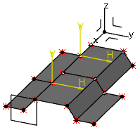 -
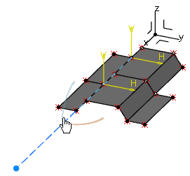
Select Curve.1 in the tree.
A handle appears at the curve extremity.
 -
Drag the handle in z direction of the positioning axis.
The curve is modified and the concept surface's color changes to red indicating that it needs an update. 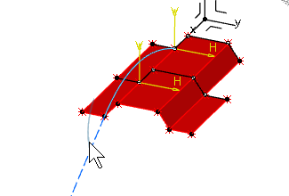 -
Release the mouse button.
The concept surface is automatically updated according to the modified curve. 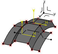
Create, Assign, and Stack Layers
You can create layers, assign them to surfaces, and combine them to layer
stackings.
-
From the View Analysis Modes section of the action bar, click Property View Mode
 to display the geometry in the colors defined in the Concept Structure Engineering specific Properties defined in the tree. to display the geometry in the colors defined in the Concept Structure Engineering specific Properties defined in the tree.
-
From the Concept section of the action bar, click Layers
 . .
The Layers Menu containing a standard Layer_1 opens and a Properties and Result (Properties)
 element is added to the tree. -
Click Add Layer.
Layer_2 is added to the list and in the Layers
 element in Properties and Result (Properties)
 in the tree. - Optional:
Click the color icon to choose another color.
-
On the Layer.2 row, right-click and select
 Assign to Surface.
-
In the work area, select one or multiple surfaces to which you want to assign Layer.2 and click
 . .
Layer.2 is assigned to the selected surfaces, and the surfaces are displayed in the layer color. 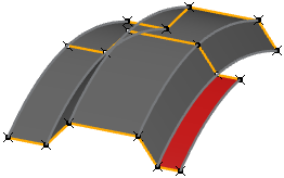 In the tree, a Properties element containing Layer_2 is added to Module.1. The Properties and Result (Properties)
 contains all layers defined in the 3D Shape. Each module contains a Properties element with the layers assigned to surfaces of the module. A check mark indicates that a layer is assigned to concept surfaces. contains all layers defined in the 3D Shape. Each module contains a Properties element with the layers assigned to surfaces of the module. A check mark indicates that a layer is assigned to concept surfaces. -
Create additional layers and assign them to surfaces.
-
From the Concept section of the action bar, click Layer Stacking
 . .
-
In the work area, successively select for each layer a surface to which the layer is assigned.
The layers are added to the Select Layers box in the Layer Stacking Creation Wizard. The first selected layer is the reference layer. The FE elements are created from this layer with an offset to the other layers. -
Click Finish.
Stacking_1 is created and added to the Properties element of the module containing the surfaces. The LAYER STACKING panel opens and a context toolbar appears.
-
In the context toolbar, click Assign Stacking
 , select one or multiple surfaces and click , select one or multiple surfaces and click  . .
The selected surfaces turn to grey indicating that a stacking is assigned. 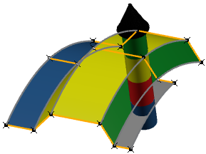
Create a Mesh
From the Concept section of the action bar, click Mesh
 .
A mesh is created from all surfaces. 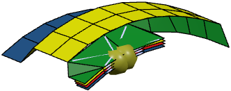 Those parts of the mesh derived from the surfaces with a layer stacking assigned are created with the layers defined in the assigned stacking. 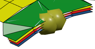
|
 .
.


