About IDF and IDX Previsualization | |||||
|
| ||||
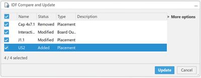
A dedicated change panel is displayed when importing, exporting, or comparing and updating IDF files. The panel names vary based on the command.
| Command Name | Panel Name |
|---|---|
| Import IDF |
IDF Import Changes |
| Export IDF |
IDF Export Changes |
| Compare and update IDF
|
IDF Compare and Update |
Likewise, a specific panel is displayed when importing, pushing, or pulling IDX files. The panel names vary based on the command. For example:
| Command Name | Panel Name |
|---|---|
| Push IDX |
EDMD Push |
| Pull IDX |
EDMD Pull |
| Import IDX |
EDMD Import |
IDF and IDX files have three possible change categories:
- Added: a new element is created.
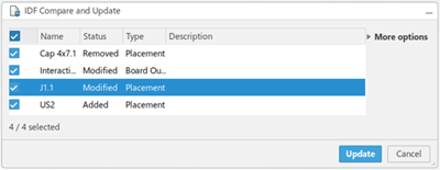
- Modified: an existing element is modified.
- Removed: an existing element is deleted.
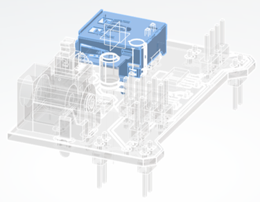
Previsualization of any element in the change panel can be unveiled in 3D by selecting or multi-selecting those elements in the change panel. All selected elements in the change panel are highlighted.
In the More options section of the IDF or IDX panel, select the Reframe on Changes option to reframe to the previsualization of the selected, changed elements and select the Ghost Representation of Context option to put background elements in a ghost representation. Any element in the change panel that is not selected, in other words, not used for previsualization, is shown as a ghost representation in 3D.
When an element is added or new, it is highlighted in blue on the 3DModel. Similarly, when an element is deleted or old, it is highlighted in red on the 3DModel. Modified elements are both blue and red with blue representing an element's read/write information to IDF or IDX. Red represents the element exiting the current 3D model.
The following image provides a graphical representation of an Added
element:

The following image provides a graphical representation of a Removed
element:

The following image provides a graphical representation of a Modified
element:
