-
From the top bar, you can create a Printed Circuit Board (PCB) by clicking . You can also search for
Printed Circuit Board at the
bottom of the New Content panel.
A new tab is opened with the new PCB.
-
Alternatively, in Circuit Board Design, click Bare Board
 from the Create
Electronic Object section of the action bar. from the Create
Electronic Object section of the action bar.
-
Click a 3D part in the tree and it becomes a PCB.
The icon of the physical product is updated to reflect the bare board assembly.
-
If you Create a 3D Part by right-clicking the physical product at the top of the tree, then
-
Right-click the 3D part in the tree and update the Title in Properties.
-
Double-click the 3D shape to open Circuit Board Design.
-
Tag the objects by clicking Board Assembly
 , then click the topmost node of the tree. , then click the topmost node of the tree.
-
Repeat for Bare Board
 at
the 3D part in the tree. at
the 3D part in the tree.
The icons in the tree have changed to reflect their updated status.
-
Click Positioned Sketch
 in the Create Part Feature section of the action bar to
begin creating a basic board.
-
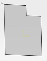
Create a closed outline with the sketch feature, then click Exit
 to exit the sketcher.
The outline of the bare board is created.
-
From the Create Layout Feature section of the action bar,
select your sketch, and click Create the board layout
 . .
-
From the Create Board Layout selection panel, update the
Name, Thickness and Board Side on
Selection.
Note:
The Board Side on Selection determines if your sketch is the
top or bottom side of your board.
Your bare board is created. Now you can design the board's layout. 
|
 > New Content > Circuit Board Design > Printed Circuit Board
 . You can also search for
  from the Create
Electronic Object section of the action bar.
 , then click the topmost node of the tree.
 at
the 3D part in the tree.
 in the Create Part Feature section of the action bar to
begin creating a basic board.
 to exit the sketcher.
The outline of the bare board is created.
 .
.
