About Forming Simulation

You can perform a simulation to verify that the plies are at their expected location after forming.

This page discusses:

Forming Simulation

Composites Forming proposes a quick simulation, sufficient at the early stage of design.

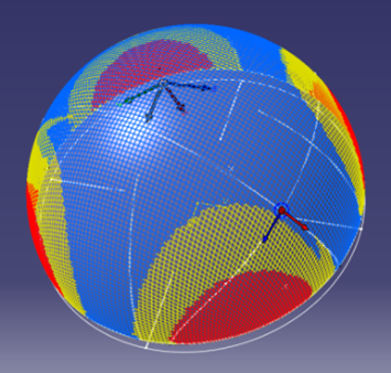
Using kinematics and inverse solvers, simulation for Hand Layup (or Draping) is very effective at modeling deformation of biaxial/uniaxial and isotropic/orthotropic materials respectively. However, for Hand Layup, the material effectively sticks to the surface at the Seed Point, with shear building up progressively from this point. The result is strongly dependent on the location of the Seed Point, and impacts the manufacturing experience.

Hand Layup:

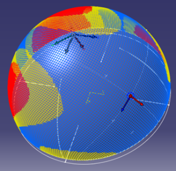
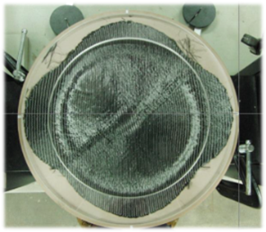
In contrast, during the forming process, the blanks slide relative to each other and to the mold, each in a very complex way. A detailed calculation of this takes hours and requires accurate material and friction data, whereas it not required nor appropriate during the initial design. A quick but representative simulation is required and sufficient at this stage.

In the absence of external constraints apart from a 3D shape, sheet materials tend to distort to minimize the global elastic energy in the sheet. Therefore, Composites Forming provides a quick solution that minimizes the shear strain energy in the sheet for a given material direction at the Reference Point. This quick solution reflects the effect of blank size and surface geometry. The material is allowed to shear at the Reference Point: Its location is not critical but is conveniently located near the middle of the ply. For the case of a symmetrical geometry like a hemisphere, the result is always symmetrical whatever the Reference Point, as expected to minimize global shear strain energy.

Forming:

Supported Materials

Composites materials used for forming can be characterized as

  • Directional, where the deformation of the fabric is strongly influenced by reinforcing fibers that lie in one or two principal directions, typical examples being woven fabrics and most uniaxial and biaxial Non-crimp fabrics (NCFs). In these materials, the reinforcing fibers can be considered inextensible and deformation during forming results mainly from shearing between the fibers. These materials drape easily and in-plane deformation can be modeled using the Pin-jointed Net (PJN) model.
  • General, where there are no obvious preferential modes of deformation and the material deforms as a function of load state and history. Typical general materials include foam, rubber, leather, random mats and triaxial or quadraxial NCFs. These materials are much less drapable than directional materials and require complex, custom material models although isotropic or orthotropic models may be acceptable for initial studies.

Material models and solvers supported by the simulation include:

  • Pin-Jointed Net (PJN) with a kinematic solver for biaxial and uniaxial directional materials.
  • Isotropic/orthotropic with an inverse solver for general materials.

A simple indentation test can be used to verify the validity of the PJN model for directional materials.

  • Example of valid PJN - Biaxial NCF (good forming)

  • Example of invalid PJN - Quadraxial NCF (bad forming, wrinkling)

Easily drapable fabrics such as biaxial and uniaxial NCFs tend to follow PJN models closely, leading to their widespread use.