Creating an Insert Manager | |
| |
-
Select the compulsory inputs.
- Select the pulling direction.
- Select the cavity side and the core side surfaces.
- Select the sketch.
- Optional:
Manage the parting plane.
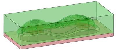
By default, Insert Manager builds core and cavity inserts with a parting plane that corresponds to the minimum of the core and cavity surfaces.

-
Select a parting plane.

-
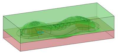
Or change the parting plane computation to correspond to the maximum of the core
and the cavity surfaces.

- Enter an offset for the parting plane.
-
Select a parting plane.
-
Optional: Manage the size and options.
By default, Manage size by offset from Core and Cavity is activated. The core and cavity inserts are build with an offset of 10mm from the top and the bottom of the plastic part. The cavity and core block size are deduced from these offsets.These offsets verify that there is enough metal to produce the inserts.
-
Alternatively, select Manage size of blocks to build the
inserts, and edit the Cavity block size and the
Core block size values.
This option specifies the size of the metal blocks used to machine the inserts.
- Optional: Enter a draft angle for interlock surfaces.
-
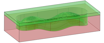
Select the Draft Mode
- Default: The neutral face is the parting plane.
- Reversed: The neutral faces are the parting surface faces.
| See Also |
| More help on this topic |