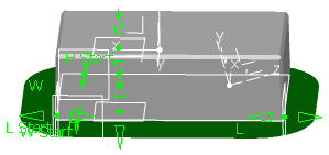
Creating a Generative Form Block

You can create a Generative Form Block from a component in an assembly structure. This Generative Form Block can then be turned into an insert in Mold Tooling Design.

A Generative Form Block is made of a pad (in the Mold Tooling Design sense),

  • The pad is created in the PartBody.
  • It can have a chamfer.
  • It can be drafted (4 drafts, one for each face).
and of a pocket ( (in the Mold Tooling Design sense, optional):
  • The pocket is created in PocketBlock.
  • It can have a fillet.
  • It can be drafted (4 drafts, one for each face).

The pad and the pocket are computed from a bounding box, based on the extremums of the surface and the intersection of 6 planes. You can move those planes to modify the bounding box, and thus the pad and the pocket.

Notes:
  • The root of the current tree must be a product.
  • If the option Restrict external selection with link to publish elements is selected, the input surface and axis system must be published.
  • We recommend that you use a published surface and a published axis system.
  • The surface must be a Mold Tooling Design surface, without any undercut, without any internal boundary and must be connex.

  1. From the Tooling Geometry section in the action bar, click Generative Form Block .
    • The root product is proposed as the Parent Product. You can select another Parent Product.
    • A 3D Part is created under the Parent Product.
    • A default Block Name is proposed once you have selected the Shape. You can enter another name, now or after having selected the Shape, before selecting the Axis System.
    • the Chamfer, Edge Fillet, Create Pocket and Draft Angle check boxes are selected.

  2. Select the inputs for the block:
    1. Select the Shape (surface to process).
      If you had left Block Name blank, a default name is proposed. You can edit it.
    2. Select the Axis System.
    A profile is proposed, built from the maximum extremums: It is resizable:
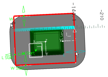
  3. Optional: Click Switch to use a profile based on the minimum extremums:


  4. Click Apply.
    A block is computed:

  5. Regarding the Pad:
    1. Clear the Chamfer check box if a chamfer is not required.
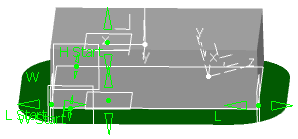
    2. If a chamfer is required, edit its Length and its Angle.
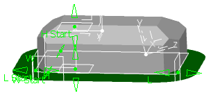
  6. Clear the Create Pocket check box if you do not want to create a pocket.
  7. If you create a pocket:
    1. Clear the Edge Fillet check box if you do not want to fillet the pocket.
    2. Otherwise, enter the radius of the edge fillet.
  8. Regarding the draft:
    1. Clear the draft angle check box if you do not want to draft the pad and the pocket.
    2. Edit the angle of the draft if you want to create one.

      The pad and the pocket are created with a 1-degree draft.

  9. Optional: Click More.
    1. Edit the Block Position.
    2. Edit the Block Size.

The pad and the pocket (if required) are created with the corresponding parameters and relations.