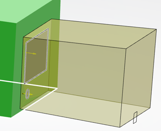
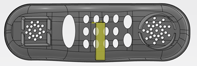
-
From the Molded Part section in the action bar, click Form Block
 .
.
-
Select the construction option from the list.
By default, the creation On shape is
proposed.
- On shape
- If only one pulling direction exists, its input shape is automatically
selected.
- If there is no hole with respect to the extrusion direction, you can validate the
feature. The Form Block is similar to a volume up the surface/volume/solid.
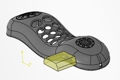
- If there are holes with respect to the extrusion direction, select a set of
surfaces to fill. The Form Block is computed from an extrude up to extremity, a
Boolean remove operation and a split by the Fill Hole.
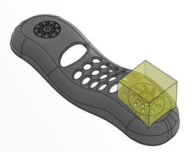
- On inserts
- This option is proposed if you select a Core Insert or a Cavity Insert. You can
also select the option.
- The Form Block is generated as an extrude up to extremity, a Boolean intersection
operation and a near.
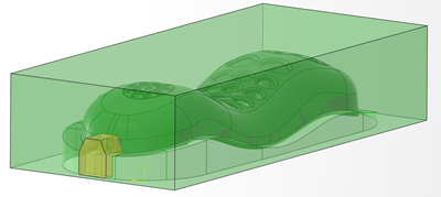
-
Select or create the sketch.
The sketch must be contained by the shape along the extrusion direction.
The
extrusion direction is as follows:
- If the sketch is outside the shape, the Form Block is generated from the sketch to
the shape.
- If the sketch is inside the part the Form Block is generated with an extrusion
direction on the nearest.
-
Select or create the shape or insert.
-
Select the Parting Line.
Using the parting line avoids leaving marks on the injected parts.
Note:
If you select
a multi-domains parting line, a Sketch Offset is mandatory.
-
Under Advanced Options, specify a Draft angle value to apply to
the border faces of the sketch.
This ensures that the mechanism that contains the Form Block can slide.

The
draft is oriented along the extrusion direction.
-
Select the Draft Mode
- Default: The neutral face is the sketch plane.
- Reversed: The neutral face is the face from the Form Block
that is embedded in the injected part.
-
Enter the value of the Parling Line Offset.
-
Select a type of Form Block, either Block,
Slider, or Lifter.
A Form Block feature is created in the tree. It contains the DraftAngle parameter.
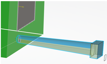
Below are some examples:
- Using a parting line, a draft angle, and an offset of the sketch.
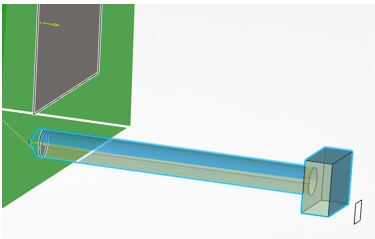
- Using a parting line, no draft angle, and an offset of the sketch.
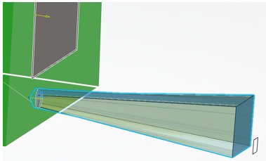
- Using a parting line, a draft angle, and no offset on the parting line.
- Using a multi-domains parting line, a draft angle, and a mandatory Sketch
Offset.
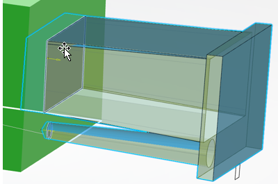
- Using no parting line, but a reversed draft with an angle.
