Creating an Insert Manager | ||
| ||
-
From the Molded Part section in the action bar, click Insert Manager
 .
.
- Optional:
Manage the parting plane.
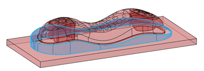
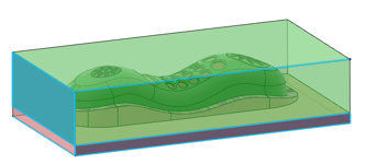
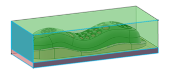
By default, Insert Manager builds core and cavity inserts with a parting plane that corresponds to the minimum of the core and cavity surfaces.
-
Select a parting plane.
-
Or change the parting plane computation to correspond to the maximum of the core
and the cavity surfaces.
- Enter an offset for the parting plane.
-
Select a parting plane.
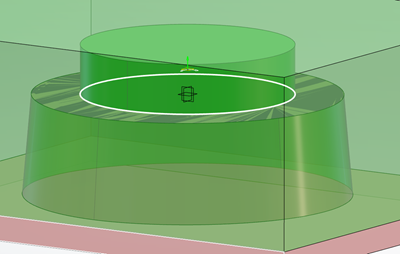
- Optional:
Enter a draft angle for interlock surfaces.
An interlock surface exists only for padding volumes, if the sketch profile is outside the side surfaces.
The draft orientation respects the unmolding of the part.
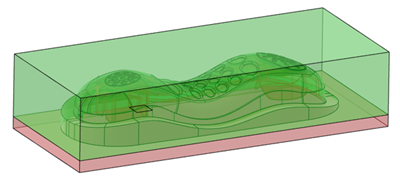
Two types of features are created under the Inserts node:
- InsertManager that is a manager with its own update, dedicated
to create and update core and cavity inserts, depending on the inputs (Pulling
direction, core and cavity side surfaces, and possibly a parting plane).Note: Parameters are stored under InsertManager
- CavityBlockSize
- CoreBlockSize
- TopOffset
- BottomOffset
- PartingPlaneOffset
- InterlockSurfaceDraftAngle
- Insert features: InsertCavity and InsertCore. Both are typed volumes.
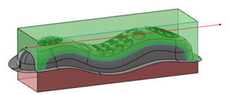
Below are some examples:
- Interlock surface, no draft.

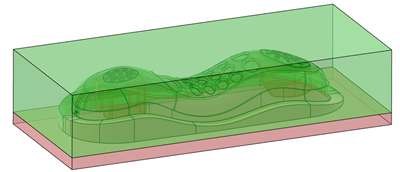
- Interlock Surface with default draft. The edge at the top of the draft is inside the
parting surface.

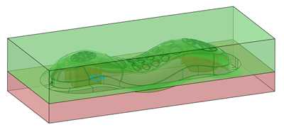
- Interlock surface with reversed draft. The edge at the top of the draft is the same as
the edge of the parting surface.
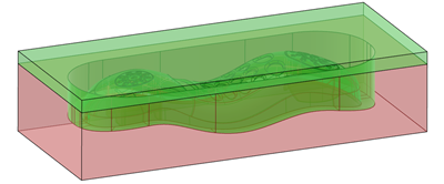
Note:
Topology can change between two constructions modes. For example, If the sketch profile
is outside the side surfaces
- When the sketch is modified but stays outside, the building strategy remains the same,
the topology follows.
- When the sketch is modified and goes inside the surface, the building strategy
changes, the topology does not always follow.