-
From the Analysis & Preparation section in the action bar, click Revolution Surfaces
 .
.
-
Select the geometrical sets created by Search Fillets to process.
-
Select the intersection plane.
- By default, the intersection plane is the xy plane.
- You can create one from the context menu.
- By default, only the revolution surfaces with their axis perpendicular to the selected plane are processed. Clear the check box to process all revolution surfaces.
-
Select the type of revolution surfaces to process.
- Closed Surfaces,
- Open Surfaces,
- or All Surfaces.
-
When you have selected
Closed Surfaces, you can filter the revolution surfaces according to their two bases.
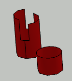
A circular basis is a true circle, like the two bases of the small cylinder, or the bottom basis
of the taller cylinder.
A non-circular basis can be an ellipse, or a circle with notches like the upper basis of the
taller cylinder.

-
Circular Bases: If both bases of the revolution surface are a
true circle, the revolution surface is processed.
-
Non-circular Basis: If at least one of its bases is non-circular,
the revolution surface is processed.
- All Bases: The revolution surface is processed, whatever the
shapes of its bases are.
-
Click Apply.
An axis and an intersection point are displayed on the revolution surfaces
found and corresponding to the filter criteria.
A geometrical set is created. Its name is
made of the prefix RevolutionSurface_ followed by the name of the first
geometrical set contained in the input geometrical set, for example
RevolutionSurface_Radius_2-3. It contains:
- A geometrical set containing the joins created from the fillets,
ConstuctionName.
- The created sketch of points. Its name is made of the name of the first geometrical set
contained in the input geometrical set and of the suffix
_Locations, for example Radius_2-3_Locations.
