Part designer
This task shows you the actions of the part designer
-
Access Collaborative Design.
-
Double-click the shape representation, then from the
Compass, select Functional Plastic Parts.
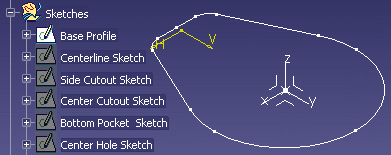
- In the tree, right-click
Base Profile located below the Sketches node and select
Hide/Show.
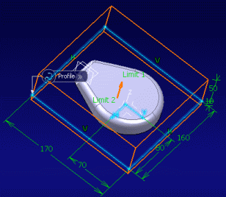
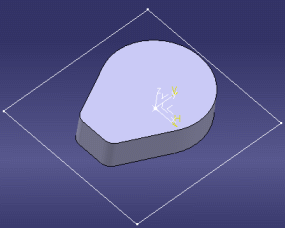
- Click Shellable Feature
 . . - Select the base profile sketch.
The Shellable Feature dialog box appears
and a preview is shown in the geometry area
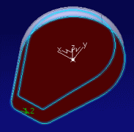
- In the dialog box, select the Draft
tab, then select Intrinsic to feature
in the Draft behavior list.
- Click OK when done.
- In the tree, right-click
Mold Block Profile located below the Sketches node and
select Hide/Show.
- In your PLM workplace, double-click the name
of the mold designer to share your design changes with this
person.
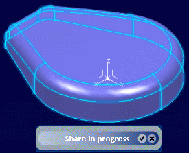
- In the Heads-Up Display, click Design Share.
- Select the Mold Block Profile in
the tree and click the Tick icon at the bottom
of the HUD to send the data to the mold designer.
- In the tree, right-click
Top Cut Surface and select Hide/Show.
- Click Cut
 . .
The Cut dialog box appears.
- Select the main body in the geometry
area: Shellable Prism.1 appears in the
Features to cut box.
- Select the top cut surface:
Top Cut Surface appears in the Cutting
element box.
- Click the arrow located on the top
cut surface to reverse the direction.
- Select the Intersection radius
check box and set the radius to 8mm, then click
OK when done.
- Right-click the top cut surface in the 3D area and select Hide/Show to hide it.
- Right-click mold block profile and select
Hide/Show to hide it.
- In the HUD, click Design Share.
- Select Main Body in the tree.
- Click Validate to send this data
to the mold designer.
Mold designer
This task shows you the actions of the mold designer
- Switch to the Functional Plastic Parts
app.
-
Access Collaborative Design.
Your Message Board indicates that
you have received shared data.
- In the Message Board, click See Received Data
 to view the data sent by the part designer.
 - Double-click the first line corresponding to
the mold block profile then click the Tick icon at the bottom
of your HUD to accept changes and integrate them into your work.
- In the Message Board, double-click
the second line corresponding to the main body then click the
Tick icon at the bottom of your HUD to accept changes.
- Insert a solid functional set Body.1,
and name it Mold Block.
- Right-click Mold Block and select
Define In Work Object.
- Click Added Feature
 . .
The Added Feature dialog
box appears:
- Select the mold block profile in the geometry
area.
- Set First Length to 50 mm.
- Set Second Length to 10 mm.
- Click OK when done.
- Right-click Mold Block and select
Hide/Show to hide it.
Part designer
This task shows you the actions of the part designer.
- In the tree, double-click
Shell Properties.1 located below Solid Functional
Set.1.
The Shell Properties dialog
box appears.
- Select the solid functional set:
Cut.1\Face.1 appears in the Faces
to remove box.
- Change the thickness to 1.2mm.
- In the Advanced tab,
change the thickness to 4mm, and select bottom face
of the main body, then click OK when
done.
- Send the shell properties to the mold designer.
- In the tree, right-click
Bottom Pocket Sketch located below the Sketches node and
select Hide/Show.
- In the Functional Features toolbar,
click Pocket
 . .
The Pocket dialog box appears.
- Select the bottom pocket sketch in the 3D area.
- Set the Floor length to 10mm in the
Distance tab.
- In the Fillet tab, select the
Floor radius check box and set the radius
to 2mm.
- Select the Protected volume check
box.
- In the Wall list, select the
Enter thickness option.
- Set the thickness to 2mm.
- In the Draft tab, select Intrinsic
to feature in the Draft behavior
list. Click OK when done.
- Send the pocket to the mold designer.
Mold designer
This task shows you the actions of the mold designer
- In the Message Board, click
See Received Data
 to view the data sent by the part designer.
 - Right-click the line corresponding to the shell
properties then click the Tick icon at the bottom of your HUD
to accept changes and integrate them into your work.
- Do the same for the pocket.
- Switch to the Generative Shape Design
app.
- Zoom in to enlarge your part.
- Right-click Sketches and select
Define In Work Object.
- Select the bottom face of the pocket (see graphic
below) and click Offset
 . .
- Click OK to close the Offset
Surface Definition dialog box
- Select the side face of the pocket (see graphic
below) and click Offset
 . .
- Click OK to close the Offset
Surface Definition dialog box.
- Select the remaining pocket face and create
a third offset surface.
- Click Join
 . .
The Join Definition dialog box appears.
- In the tree, select
Offset.1, Offset.2, and
Offset.3.
- Click OK when done.
- In the tree, right-click
Mold Block Profile (below the Mold Block/Solid Functional
Set.2 node) and select Hide/Show.
The profile appears.
- Select the mold block profile in the geometry
area and click Fill
 . .
- Click OK in the Fill Surface
Definition dialog box that appears.
- Right-click Main Body in the tree and select Hide\Show.
- Zoom out, right-click Mold Block Profile
and select Hide\Show.
- Click Trim
 . .
The Trim Definition dialog
box appears.
- Select Join.1 in the tree.
- Select Fill.1 in the tree.
- Click OK when done.
- Switch to the Functional Plastic Parts
app.
- Right-click Mold Block in the tree and select Hide/Show.
The mold block appears. - Right-click Mold Block in the tree and select Define in Work Object.
- In the Multi-body Features toolbar,
click Divide
 . .
The Divide dialog box appears.
Mold Body is selected in the Body to divide
box.
Divide Body.2 and Divide Body.3
are created.
- Select Trim.1 from the tree for Divide element.
- Click OK when done.
- Rename Divide Body.2 and Divide Body.3
to Upper Mold Block and Lower Mold Block.
- Right-click Mold Block in the tree and select Hide/Show to hide the mold block.
- Right-click Lower Mold Block in the
tree and select Hide/Show to hide the
lower mold block.
- In the tree, right-click
Upper Mold Block and select Hide/Show to hide
the upper mold block, then right-click Lower Mold Block
and select Hide/Show to display the lower mold block.
- Right-click Lower Mold Block in the
tree and select Hide/Show.
- Right-click Main Body and select
Hide/Show.
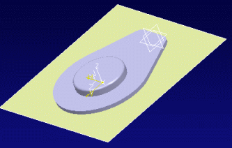
The main body appears.
Part designer
This task shows you the actions of the part designer
- In the tree, right-click
Middle Ribs located below the Sketches node and select
Hide/Show.
The ribs sketch appears. - Click Rib
 . .
The Rib dialog box appears:
- Select the ribs in the 3D area.
- In the Distance tab, set First
limit to To shell.
- Click Reverse Direction.
- In the Thin Solid list, select
Enter thickness and set the thickness
to 3mm.
- In the Draft tab, set Draft
behavior to Intrinsic to feature.
- Click OK when done.
- In the tree, right-click
Outer Ribs Sketch located below the Sketches node and
select Hide/Show.
The outer ribs sketch appears. - Click Rib
 . .
The Rib dialog box appears:
- Select the outer ribs in the 3D area.
- In the Distance tab, set First
limit to To shell.
- Click Reverse Direction.
- In the Thin Solid list, select
Enter thickness and set the thickness
to 20mm.
- In the Draft tab, set Draft
behavior to Intrinsic to feature.
- Click OK when done.
- Select Rib.1 and Rib.2
in the tree and send to the mold designer.
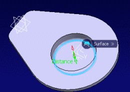
- In the tree, right-click
Center Hole located below the Sketches node and select
Hide/Show.
The center hole sketch appears. - Click Cutout
 . .
The Cutout dialog box appears.
- Select the center hole sketch in the 3D area.
- In the Distance tab, set Floor
to Through All.
- Set Wall to Enter thickness
and set the thickness to 0.
- Click OK when done.
- Select the cutout you have just created in the
tree and send it to the mold designer.
- In the tree, right-click
Side Cutout Sketch and Center Cutout Sketch
located below the Sketches node and select Hide/Show.
The sketches display. - Click Cutout
 . .
The Cutout dialog box appears.
- Select the center cutout sketch in the 3D area.
- In the Distance tab, set Floor
length to 28mm.
- Click Reverse Direction.
- In the Draft tab, set Draft
behavior to Intrinsic to feature.
- Click OK when done.
- Click Cutout
 . .
The Cutout dialog box appears.
- Select the side cutout sketch in the 3D area.
- In the Distance tab, set Floor
length to 36mm.
- Click Reverse Direction.
- In the Draft tab, set Draft
behavior to Intrinsic to feature.
- Click OK when done.
- Select the two cutouts you have just created
in the tree and send them to the mold designer.
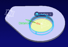
- In the tree, right-click
Bolt Hole located below the Sketches node and select
Hide/Show.
The bolt hole Sketch appears. - Click Cutout
 . .
The Cutout dialog box appears.
- Select the bolt hole sketch in the 3D area.
- In the Distance tab, set Floor
to Through All.
- Click OK when done.
- Select the cutout you have just created (Cutout.4)
in the tree and send to the mold designer. You
are done with the design.
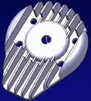
Your final part looks something like this:
Mold designer
This task shows you the actions of the mold designer
- In the Message Board, click
See Received Data
 to view the data sent by the part designer.
 - Right-click each line then click the Tick icon
at the bottom of your HUD to accept the ribs, center hole, center-side
cutouts and bolt hole, and integrate them into your work.
- Expand the Solid Functional Set node,
then right-click Cutout.4 and select Cutout.4
object > Deactivate.
- Right-click Cutout.1 and select
Cutout.1 object > Deactivate.
- Select Lower Mold Block in the tree, and select Hide/Show to display the lower mold
block.
- Right click Lower Mold Block and
select Define in Work Object.
- Click Fitting
 . .
The Fitting dialog box appears.
- Select Main Body in the tree. Main Body appears in the Tool body
box.
- Set Clearance to 1mm.
- Click OK when done.
- Right-click Upper Mold Block and
select Define in Work Object.
- Right-click Lower Mold Block and
select Hide/Show.
- Right-click Main Body under the
Lower Mold Block and select Hide/Show.
- Click Fitting
 . .
The Fitting dialog box appears
- Select Main Body in the tree. Main Body appears in the Tool body
box.
- Leave the same clearance.
- Click OK when done.
- Right-click Upper Mold Block and
select Hide/Show. Hide it again.
- Right-click Lower Mold Block and
select Hide/Show. The lower mold block appears.
|
 .
.


 .
.

 to view the data sent by the part designer.
