The
Bridge Design Assistant helps you design the deck
and support elements of a bridge starting from a simple schematic wireframe
model to the generation of a detailed 3D model. This assistant allows you to
study various design solutions and lets you easily edit the design taking
constraints into account.
The design of the bridge is facilitated by the usage of object types and
its edition is easily manageable in the
tree.
Bridge elements must be defined with valid object types when
using
Bridge Design Assistant.
Object Type Definition
The definition rules for a valid bridge-related object type are the
following:
The object type must contain a Feature-Based Design model with
an axis system input named "Base Axis System".
For object type inputs:
Other inputs must not be added to reference object types.
Specific inputs can be optionally added to adaptive and
distribution object types.
For object type outputs: specific outputs can be optionally added
to some object types.
Note:
Optionally, an object type can contain configurations.
Specific Inputs and Outputs
Function in the bridge
List of available types
Optional inputs
Optional outputs
Deck
Deck
Span
Mandatorily, Base Axis System corresponding to deck/span start
extremity. Usually, it lies on alignment.
Optionally, a supplementary axis system
corresponding to deck/span end extremity, named
End Axis System.
If it exists, a sequential next axis pattern is
automatically generated to define it under Deck
Set.
If there exists only one axis system input
(excluding Base Axis
System), it can be of any name, with
advised name End Axis
System. Otherwise, it is ignored, and
you must manage it by editing Deck Set.
Optionally, a guiding curve, named Alignment. If there exists
only one curve input, it can be of any name. The
advised name is Alignment.
Otherwise, it is ignored, and you must manage it by
editing its corresponding Support Set.
Optionally, other inputs. You must manage them by
editing Deck Set.
Optionally, two axis systems with given names
Input for support 1 and
Input for support 2.
If such outputs exist, they must mandatorily
correspond to the position of supports.
Otherwise, the support positions are computed by
the shift of alignment downward to ground with an
offset value equal to deck height. In this case,
make sure that the deck height defined in the
bridge layout is compatible with the actual deck
height in user-feature.
Optionally support system outputs. If the inputs
of support elements require support system
meta-inputs, then the outputs of deck support
system must contain the geometrical outputs with
names defined in the meta-inputs.
Example: The support system meta-input
Span 1 of the middle
support requires two geometrical elements named
Support system surface front
2, and Front 2 of the
span. All deck/span user features must
contain two outputs of the same names.
Middle supports
Pier
Pile
Crosshead
Tower
Mandatorily, Base Axis System
corresponding to support origin.
Optionally, a ground level point, named
Point on Ground.
If it exists, a projection pattern is
automatically generated to define it under Support
Set, by projecting the origins of Base
Axis System on the terrain.
If there is only one point input, it can be of
any name, with advised name Point on
Ground. Otherwise, it is ignored, and
you must manage it by editing Support Set.
Optionally, two support systems, defined as
meta-inputs (not geometrical inputs), mandatorily
named Span 1 and
Span 2, corresponding respectively to
support system outputs at deck/span start and end
extremities.
The meta-input is defined by a list of any number
of geometrical elements with given names. The deck
outputs must contain all geometrical elements of
same names as those defined in the
meta-inputs.
Example: Span 1 is defined
by two geometrical elements named
Support system surface front
2, and Front 2 of the
span. All span/deck user feature
outputs must contain at least two outputs of the
same names, Support system surface
front 2 and Front 2 of the
span. Otherwise, the pattern update
will fail.
For each support system, a selection pattern is
automatically generated. It takes the user feature
results from Deck Set as
input. Before the creation of the selection
pattern, all deck user features must have been
instantiated.
The support system inputs are permitted under two conditions:
The bridge must be isostatic, since they need
outputs for all spans, and non-isostatic bridge
cannot generate outputs for all spans.
All deck/span user features must contain all
geometrical outputs with their names defined in
the inputs of the support system meta-inputs.
Optionally, a guiding curve, named
Alignment. If there exists
only one curve input, it can be of any name. The
advised name is Alignment.
Otherwise, it is ignored, and you must manage it by
editing its corresponding Support Set.
Optionally, other inputs. You must manage them by
editing the Support Set.
No specific outputs.
Start and end supports
Abutment
Pier
All remarks about middle supports apply to start and end supports, except for support
system.
Optionally, one support system, defined as
meta-input (not geometrical input), mandatorily
named Span, corresponding
to deck/span support system outputs at start or
end extremities.
All other remarks about middle support system
inputs apply to start and end support system
input.
Optionally, a guiding curve, named
Alignment. If there exists
only one curve input, it can be of any name. The
advised name is Alignment.
Otherwise, it is ignored, and you must manage it by
editing its corresponding Support Set.
No specific outputs.
Bridge Parameters
The
Bridge Design Assistant defines the following
bridge parameters: Deck Height, Support Length, Tower Height, Abutment Height,
Abutment Length and Abutment Seat Length.
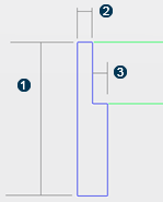
The meaning of each parameter is illustrated by the two figures below:
A deck and supports
Deck Height
Alignment
Support Length
Tower Height
An abutment
Abutment Height
Abutment Length
Abutment Seat Length
Mapping between bridge parameters and object type parameters
The
Bridge Design Assistant defines a list of bridge
parameters that you can edit directly in the
Bridge Design Assistant.
On the other side, when object types are assigned to different bridge
elements, some object types define their own parameters.
A mapping between the bridge parameters and parameters of object types
is shown in the table below. If both names match, the corresponding parameter
of object types is set equal to its related bridge parameter, and the bridge
parameter is the driving parameter.
Bridge Parameter
Object Type
Parameter Name Object Type
Deck Height
Deck, Span, Span Segment
Height
Support Length
Pier, Tower
Length
Tower Height
Tower
Height
Abutment Height
Abutment
Height
Abutment Length
Abutment
Length
Abutment Seat Length
Abutment
Seat Length
For example, if a deck, span, or span segment object type contains a
parameter named “Height”, a relation “Height = Deck Height” will be created, so
that the deck height of instantiated user feature will be equal to “Deck
Height” defined in the bridge design. If you modify the valued of “Deck
Height”, the corresponding user features will be updated, and its height
remains equal to the new “Deck Height”.
A bridge parameter applies to a given list of object types. For
example, “Abutment Height” is only meaningful to abutments. It does not apply
to other object types. But “Support Length” applies both to pier and tower
object types.
The mapping is case-sensitive.
The Tree
After the 3D generation of your bridge, specific bridge-nodes
appear in the
tree.
Bridge specifications are aggregated under the Bridge Set node as
follows:
Bridge Layout Set: A geometrical set containing the bridge layout
feature results (the Deck and Support Layout Sets that are the component-based
design).
Bridge Deck Set
Bridge Start Support Set
Bridge Middle Support Set
Bridge End Support Set
Bridge results are aggregated under two different nodes created
automatically by the Bridge Design Assistant:
Bridge Deck Results
Bridge Support Results
Clicking the Bridge Set node allows you to edit the bridge
specifications after the bridge generation.

 Deck Height
 Alignment
 Support Length
 Tower Height