Experiencing Simulations on 3D Alignments

You can create simulations using cameras to experience and review your road or railway design in a simple and interactive manner.

A traveling camera is placed in a way that emulates the vision of the vehicle driver according to vehicle specifications. The camera follows the designed road or railway. You can see your design in use, identify unforeseen visibility problems, and review your project.

This task shows you how to:


Before you begin:
  • Open civil data containing a terrain.
  • Create a 3D alignment.

Launch an Automatic Camera Traveling

You can select an alignment and handle camera positioning and movement according to your preferences.

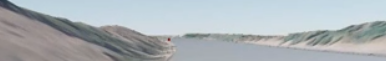
The Play command allows you to review your design and detect a potential obstacle or crest on the route that may obstruct the driver's vision. Then, you can adjust your design security-wise.

  1. From the Road or Railway section of the action bar, click Play .
  2. Select an alignment curve.

    If the 3D Shape contains more than one alignment, the list is displayed in a panel and you can select one of them.

    The Play button triggers an automatic camera traveling along the curves corresponding to the central alignment or curve offsets from the central alignment. The camera follows the alignment, moving left, right, up, and down according to the alignment curvature, to simulate a driver’s vision.

    A Play section also appears in the action bar. For more information, see Manage the Animation Progress.

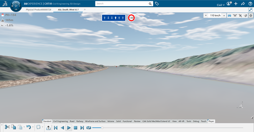
    Various types of information relative to the camera’s eye current position on the alignment are displayed on the user interface and you can define specific camera behaviors. For more information, see the following sections.

    The 3D Alignment can contain event points that surcharge the design speed and the lane distribution. The camera's eye takes the information into account. When it reaches the first event point as well as the position of the stopping sight distance marker that is calculated thanks to it, the design speed varies. When the camera's eye reaches the second event point, the lane distribution changes.

Manage the Animation Progress

You can use animating simulation results to see the progression of the model through the simulation.

  1. From the Road or Railway section of the action bar, click Play .

    The app animates the current results.

    Note: The Options panel lists the available shortcuts to better match your needs for navigating your 3D alignment.

    The Play section also appears in the action bar, providing control buttons and a slider that shows the progress of the animation.

  2. According to the available simulation results, click Options to change the animation of the results.
    Option Description
    Jumps to the beginning of the animation frame.
    Plays in reverse.
    Plays.
    Stops.
    Pauses.
    Jumps to the end of the animation frame.
    Launches a continuous loop.
  3. Click 
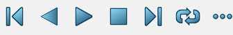
to close the animation player.

Change the Simulation Layout

The camera is placed at vision height according to the vehicle specifications, and can be manipulated through the user interface or keyboards shortcuts.

  1. To modify the interface information, click Options :
    Visualization Information Description

    Clears the options in Display to hide the following information:

    • Station: Current stationing.
    • Elevation: It can be geolocated if the product was associated with a geolocation, or local if it was not.
    • Grade : The level and gradient.

    or

    A Round or Square sign for the design speed limit.

    To determine at which speed the camera travels by default (editable). It can be overridden by the lane speed and alignment points surcharging the design speed.

    Current lane distribution (editable): Lets you choose which lane you want to travel the alignment. The traveled lane is highlighted as a white arrow.

    Note: An upward arrow means that the camera is traveling from the alignment start to the alignment end. A downward arrow signifies a lane going in the opposite direction of the traveling.
    Visualization modes: Click a button to switch the camera mode.
    • First-person Viewpoint: The camera position is at the height of the user's eyes.

    • Third-person Viewpoint: The camera is moved away to increase the angle of the camera and reduce occlusion.

    • Overhead-far Viewpoint: The camera is placed high above the alignment to have an overview.

    • Sectioning Viewpoint: The camera position is at the height of the user’s eyes, a section plane is displayed a few meters further to reveal underground information. For example:

    Note: The Options panel lists the available shortcuts to better match your needs for navigating your 3D alignment. For more information, see Use Shortcuts.
  2. To modify the Visibility control, click Options .
    Visualization Information Description

    Stopping Sight Distance: A red marker that is placed at the stopping sight distance, calculated according to the current design speed and to the design vehicle in a road case. One point of the marker is placed at the road level. The other is placed at the vision height level. The marker is moved at the same time as the camera.

    Note: It is useful to see when the road design has visibility problems. For example, the stopping sight distance marker is obscured by a building, meaning that if an obstacle is present at the stopping sight distance, the road user cannot stop the vehicle in time to avoid it.

    Vehicle: When selected, the vehicle is visible in two different ways.

    This is the design vehicle of the alignment. It is used to determine the vision height for the camera placement as well as the deceleration rate for the calculation of the stopping sight distance.

  3. Optional: Use shortcuts as described in the section below.

Use Shortcuts

The camera is placed above the central alignment and elevated at a height that can be modified by the user with keyboard shortcuts.

  1. Choose a visualization mode by clicking alternatively the required camera mode icon at the upper right of the screen.

    For more information about the viewpoints, see Change the Simulation Layout.

    The camera’s target is placed at road level, 50 meters (in curvilinear distance) from where the camera’s eye is projected on the road, ahead of the lane.
  2. Change the offset with keyboard shortcuts.

    You can make the camera’s direction rotate, allowing you to better see the alignment’s surrounding, as if you were turning your head.

    Key of the Numeric Pad Action
    Switches camera mode.
    Speeds up.
    Slows down.
    Switches to the right lane.
    Switches to the left lane.

    First-person viewpoint: Rotates the camera to the left.

    Third-person viewpoint: Offsets traveling path to the left.

    Overhead-far viewpoint: NA.

    Sectioning Viewpoint: NA.

    First-person viewpoint: Rotates the camera to the right.

    Third-person viewpoint: Offsets traveling path to the right.

    Overhead-far viewpoint: NA.

    Sectioning Viewpoint: NA.

    First-person viewpoint: NA.

    Third-person viewpoint: Elevates the camera.

    Overhead-far viewpoint: Elevates the camera.

    Sectioning Viewpoint: NA.

    First-person viewpoint: NA.

    Third-person viewpoint: Lowers the camera.

    Overhead-far viewpoint: Lowers the camera.

    Sectioning Viewpoint: NA.