Creating a Horizontal Alignment | |
| |
-
From the Road and Railway section
of the action bar, click Horizontal Alignment
 .
In the Alignment Sketcher, an alignment assistant guides you through the process of establishing the path of your linear construction by defining alignment options along with stationing parameters.
.
In the Alignment Sketcher, an alignment assistant guides you through the process of establishing the path of your linear construction by defining alignment options along with stationing parameters. -
Choose the Road or Highway
configuration.

Each configuration corresponds to a road/highway profile that can be defined with Data Setup.
After selecting an existing profile (road or highway), you can modify the following attributes:
- Profile Specifications: Profiles, travel way/shoulder lanes distribution and vehicles
types are stored and managed in an xml file in Data Setup, called in the RoadAlignmentDesign.xml for road
design.
To create a customized road, you can directly modify some attributes and click OK to validate. For road surface widening, you can edit the Right shoulder slope, Widening transition/smoothing and Roll-over angle (not to have a large slope between the travel way and the shoulder). The customization is only local to the edited 3D Shape and does not impact Data Setup.
Road specifications can also be modified from a given station using Alignment point dialog box.
- Traveled way lane distribution: when there is
no lane definition, only
 is
available. To define it, select an existing lane type or create one
by clicking .
is
available. To define it, select an existing lane type or create one
by clicking . - Shoulder lane distribution: To define it,
select an existing lane type or create a new one by clicking .
- Rules: correspond to the selected profiles, managed in Data Setup. You cannot edit them.
Tips: Road specifications and traveled way lane/shoulder lane distribution can also be modified from a given station using the Alignment point dialog box. In the Horizontal Alignment Initialization and the Alignment Point dialog boxes, customization is only local to the edited 3D Shape and does not impact the Data Setup.
You can choose a Type in the Lane section:
- Planar: the shape of the road provides a straight plane, with one slope.
- Crown: the shape of the road provides a sloped plane, forming a crown, with two slopes joining at the center.
You can change the surface position by selecting a Rotation Mode. The available alignment types are:
- Centerline: The traveled way revolves about the centerline.
- Inner edge: The traveled way revolves about the inside turn.
- Outer edge: The traveled way revolves about the outside turn.
- Left: The traveled way revolves about the left edge.
- Right: The traveled way revolves about the right edge.
- Center of central median: The traveled way revolves about the
center of the central median.
This rotation mode needs a central lane that cannot be used by vehicles. If none exists in the model, it is created. If it can be traveled, it is replaced by another one that cannot be traveled. The central median pilots the rotation around its center. The left and right slopes rotate less and follow the central median's rotation.
- Edge of central median: The traveled way revolves about the
extremities of the central median that does not rotate. The
rotation on the left and right sides behaves like
Centerline.
The behavior of the central lane specifications is the same as with Center of central median.
When a rotation is used, an Extract feature appears under the Traveled way node aggregated in Road Surface, in the tree. If you select the Center of central median or Edge of central median modes, the Switch
 button
replaces the Remove
button
replaces the Remove
 button.
When one of the other modes is selected, the
Remove button replaces the
Switch button.
button.
When one of the other modes is selected, the
Remove button replaces the
Switch button.Rotation modes can be customized with Data Setup. The travel way type and rotation mode can be changed in the Specification panel only (cannot be edited in the Alignment Point dialog box).
- Profile Specifications: Profiles, travel way/shoulder lanes distribution and vehicles
types are stored and managed in an xml file in Data Setup, called in the RoadAlignmentDesign.xml for road
design.
-
To edit profiles specifications, click
 to switch to the edition
mode. Then modify attributes, for example speed, and click
OK to validate.
to switch to the edition
mode. Then modify attributes, for example speed, and click
OK to validate.
Tips: - When a value is overloaded, its name turns bold.
- Click Reset
 to
revert to the previous specifications.
to
revert to the previous specifications.
-
To add a new lane, click in the
Traveled way lane distribution section. In the
Lane Chooser dialog box, you can do the
following:
- Select a lane type: select an existing lane or create a new one.
- Change Lane specifications: when the selected lane has a
traveling direction set to One way, a right/left
arrow is displayed next to the Remove
 button.
To inverse the traveling direction, click the arrow.
button.
To inverse the traveling direction, click the arrow. - Edit Vehicle parameters: the selection of a vehicle type automatically increases the lane width if the vehicle does not fit the lane.
-
To create your profile, click Alignment Profile
 .
.
The profile must be continuous.
-
To create the profile alignment, select the design options of your choice in
the Alignment Assistant:
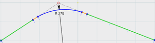
- Curve creation: lets you automatically create a
curve at each angle (in blue in the image below).
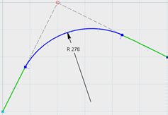
- Spiral creation: lets you automatically create a spiral (spiral
in orange in the image below) before and after each curve. Select one of the
following types to create a transition between two curves:
- Clothoid
- Cubic parabola
- Cosinusoidal
- Sinusoidal
- Dynamic constraints: The option is selected by default.
During the alignment design profile, constraint detection made by the Sketcher assistant is deactivated to avoid over-constrained sketches (length and tangency constraints are not detected). Detection options are automatically cleared in the SmartPick... panel. You can open them in the Constraint section of .
Only coincidence constraints are detected and created. If you want to visualize more detection information, you can force them in , by clicking SmartPick...
When you exit the alignment workshop, the detection options are restored except if you have forced them during the alignment profile command.
- Click
 to
display the geometric elements in specific colors based on their diagnostic
solving status.
to
display the geometric elements in specific colors based on their diagnostic
solving status.
- Curve creation: lets you automatically create a
curve at each angle (in blue in the image below).
-
Optional: To display the stationing and visualize the road or
railway, click Visualization
 from the
Alignment section.
The horizontal alignment is created.
from the
Alignment section.
The horizontal alignment is created.