Creating a Platform Earthwork | |
| |
-
From the Civil Engineering section of the action bar, click Platform Earthwork
 .
.
-
To select a platform cross section containing predefined
excavation and filling profiles, do one of the following:
-
Select a platform cross section in the
Cross Section node in the
tree
when it is available in the same assembly. Or click
Search an object type
 .
.
Only object types corresponding to the chosen discipline (which can be a platform, a road, or a railway) and undefined object types are visible. The content provided in the SubgradeTypicalCrossSections.3dxml stored in the
...\startup\Civil\Alignmentdirectory has been updated in R2022x GA to take the discipline into account. - Select a platform cross section in the list.
- Optional: Sketch a new profile.
-
To remove the cross section, click
 .
.
-
Select a platform cross section in the
Cross Section node in the
tree
when it is available in the same assembly. Or click
Search an object type
-
Optional: To display a preview of the selected object type in a
side panel, click Template Helper
 .
A template viewer opens next to the Platform Earthwork dialog box and displays the shape of the object type and axis systems.
.
A template viewer opens next to the Platform Earthwork dialog box and displays the shape of the object type and axis systems.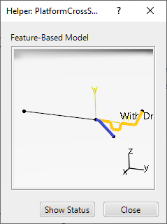
In the Helper, you can move and zoom in the object type. Click again the same input and the object type moves back to its initial position.
To close the Helper, click
 or Close or
 - Optional:
From the Civil Engineering section of the action bar, click BIM
Attributes
 and select the Excavation or Filling works in the tree to read the excavation and filling volumes
(in the Bank volume box).
and select the Excavation or Filling works in the tree to read the excavation and filling volumes
(in the Bank volume box).
-
To edit the cross section, select Platform Stretch Set
in the tree and click
 under the
Platform Cross Section area in the
Platform Earthwork dialog box.
under the
Platform Cross Section area in the
Platform Earthwork dialog box.