Design the Layers of a Subgrade
You can design the layers of a subgrade thanks to a user-defined typical cross section.
-
To create a subgrade, click Road/Railway Subgrade
 from
the Road or Railway section of the action bar
and do the following:
from
the Road or Railway section of the action bar
and do the following:
- Select an alignment to sweep along it.
-
Select an Object Type having the Subgrade type.
Only object types corresponding to the chosen discipline (which can be a platform, a road, or a railway) and undefined object types are visible. The content provided in the SubgradeTypicalCrossSections.3dxml stored in the
...\startup\Civil\Alignmentdirectory has been updated in R2022x GA to take the discipline into account.
-
In Parameters, use the following options to:
-
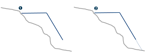
Extrapolate cross section to terrain: available (selected
by default) in the earthwork context only, when excavation and filling profiles have
been defined in the UDF of the object type. To extrapolate the last section of the
cross section profile to the terrain, select the option. The cross section profile
is systematically extrapolated to the terrain, as shown in the right image
below.
To keep the profile as it is (as shown in the left image below), without extrapolation, clear the option.
 : Right side profile
without extrapolation.
: Right side profile
without extrapolation.  : Right side profile
with extrapolation.
: Right side profile
with extrapolation. -
Define a precision computation:
- Coarse: to operate with user-defined cross sections only. This computation mode is quick but less precise.
- Medium: for a quick but less precise computation.
- Fine: may be time-consuming.
- Manual: when selected, the Step box appears under the Precision modes. Set the step value to define the maximum distance between profiles along the alignment. Subgrade and Earthwork surface computation (including Preview) is based on these computed profiles.
-
Extrapolate cross section to terrain: available (selected
by default) in the earthwork context only, when excavation and filling profiles have
been defined in the UDF of the object type. To extrapolate the last section of the
cross section profile to the terrain, select the option. The cross section profile
is systematically extrapolated to the terrain, as shown in the right image
below.
-
To edit sections, do the following:
- Set parameters on sections. By default, there is a start and end section. Each section must have the same number of edges and vertices along the swept volume.
- Select the contextual command to display or hide parameters on a section in the 3D area.
-
Add a new section by clicking
 and selecting a point
on alignment for example. The new section inherits the previous section's
parameters. When you have three sections, additional contextual commands are
available: Remove and Order sections along the
alignment.
and selecting a point
on alignment for example. The new section inherits the previous section's
parameters. When you have three sections, additional contextual commands are
available: Remove and Order sections along the
alignment.
You can define transitions between sections without creating additional sections. See next step.