Creating a UDF- or Sketch-based Typical Cross Section and Associated Object Types for Earthworks

You can also create object types of subgrade types that can be reused in the Road Earthwork or Railway Earthwork command.

For information about object types, see Building and Civil Assemblies User's Guide: Defining Object Types.

This task shows you how to:

Create a Sketcher-based Typical Cross Section

You can create a typical cross section that is an input necessary for earthwork design.

  1. To create a sketcher-based typical cross section, from the Civil Engineering section of the action bar, click Typical Cross Section to create a void typical cross section.
  2. From the Typical Cross Section section of the action bar, click Excavation Profile .

    You must create two side profiles. It consists of two polylines, each corresponding to one side of the road/railway.

  3. Draw the first side of the excavation profile in the 3D area and double-click anywhere to validate.
  4. Repeat the same step for the second side or click to generate the side 2 Profile symmetrical to the side 1 Profile automatically.

    If side 2 Profile exists, it is replaced by the newly created symmetrical profile.

    The Typical Cross Section node is created in tree.
  5. Click OK to create a 3D output profile corresponding to the excavation profile.
    The excavation profile is created in the tree or the 3D area. It represents the geometry that will be removed from the ground. You can edit the profiles in the same way as for any sketch polyline.
    Tip: After creating the profile, the status icon is green and the Create side 1 profile button changes into Edit side 1 profile in the Excavation Profile window.
  6. To add segments to the first created profile, click Edit side 1 profile next to .
    The cursor automatically moves at the end of the profile and you can add other segments to the existing profile. Repeat the same step on the second side of the profile if needed. To delete this side of the profile, click .
  7. From the Typical Cross Section section of the action bar, click Filling Profile .
  8. Click Exit to go back to the Civil Engineering 3D Design.

Create Typical Cross Section based on User Defined Feature

You can create a typical cross section that is an input necessary for earthwork design.

  1. To generate excavation and filling surfaces in layer subgrades, you need to add excavation and filling profiles as outputs of the user-defined feature (UDF).

    If the cross section is UDF-based and has geometrical inputs named Base Surface or Base Alignment, the input surface of the earthwork will automatically be assigned to the UDF input called Base Surface, the input alignment to the UDF input called Base Alignment. You can change these inputs manually.

    When you define a UDF as a typical cross section, the UDF must have:
    • A Base Axis System as input. It can have additional inputs.
      Tip: To set a Base Axis System as an input of the UDF, do the following:
      • click Formula from the Tools section of the action bar.
      • Select Axis System in the New Parameter of type list.
      • Click New Parameter of type and Add Formula and, select Axis System. Click Update. The tree is modified accordingly with the f(x) Axis System.
      • In the tree, replace the initial axis system with the Formula axis system.
      • From the Civil Engineering section of the action bar, click User Feature Definition and select Axis System in the
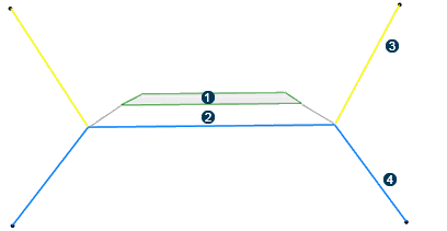
 Inputs of components panel of the User Feature Definition dialog box.

      The Base Axis System is an input of the UDF.

    • Exposed parameters that will be retrieved in the Subgrade command.
    • Opened or closed curves as outputs.

    Excavation and filling profiles are added to the subgrade cross section. The schema below illustrates about the railway structure:


    Subgrade layer 1

    Subgrade layer 2

    Excavation profile

    Filling profile

  2. To type the outputs of the subgrade, type the main result and/or the outputs of the UDF. For this, do the following:
    • Open the part containing the UDF and click Define Specification from the Civil Engineering section of the action bar.
    • Select Excavation works type in the Define Specification panel, and the excavation profile in the tree.

    • Select Filling works type in the Define Specification dialog box, and the filling profile in the tree.
    Tip: To check if the output is typed, click BIM Attributes from the Civil Engineering section of the action bar.

    A typical cross section is created.

Create a Subgrade Object Type and Attach a Typical Cross Section to This Object Type

You can create a subgrade object type, and attach the above created typical cross section to it. Subgrade object type is not only used in subgrade design, but also in earthwork design.

  1. Click Add > Content and select Subgrade Type.
    A dialog box appears enabling you to create an object type of subgrade type.
  2. Choose a title and select the Adaptive mode for the Product instantiation method.
    You have created an object type that can be reused in Road/Railway design. With the Adaptive mode, the profile starts and ends on the alignment segment. The connection to one of the profile extremities allows to position the profile relatively to the roadway/railway. Thus it is possible to position the cross section relative to roadway/railway during the sweep creation along the alignment.
  3. Click OK.
    The subgrade object type is created along with the associated typical cross section. The Resource Table of the object type contains a table called Cross Section. Its type is Sketch, only available on a limited list of object types. The cross section created in object types must be created by the cross section sketcher.
  4. Double-click Resource table in the tree.
    The Resource Table Management dialog box appears.
  5. In the Resource Table Management dialog box, choose either of the lines:
    • Cross Section: with sketch type.
    • Cross section with Feature-based Design: with a UDF type.
  6. Right-click the Resource cell and select Choose the assigned resource.
  7. Select the Typical Cross Section or a UDF in the tree or the 3D area and, click OK.
  8. Click OK in the resource table.
  9. Select Share > Save > Save All to save the created object type.

The typical cross section is attached to the subgrade object type.