Creating a Stretch Set | |
| |
-
From the Civil Engineering/Road/Railway section of the action bar,
click Civil Set/ Road Set/Railway
Set
 .
The Civil/Road/Railway Set dialog box is displayed. A Stretch Set feature called Civil Set or Road Set or Railway Set is created in the tree under the Civil Engineering or Road or Railway node depending on the selected command. If the input surfaces of the stretch set intersect or are in contact, the terrain modification cannot be done.
 -
To consolidate earthworks and/or subgrade layers, select the results you want to
compute in the Generate list:
- All: consolidates both earthworks and subgrade layers.
- Only terrain-related results: consolidates only earthworks.
- Only subgrade layers: consolidates only subgrade layers.
The stretch set command can accept subgrades and earthworks. The inputs of stretch set may contain earthworks and/or subgrade layers. You can consolidate subgrade layers in one stretch set, and terrain-related results in another one.
- To modify the terrain or create consolidated subgrade layers, select the necessary inputs in the Civil/Road/Railway Set dialog box.
- Optional:
To select a destination set (choose the Civil/Road/Railway Set in which the stretch set
will be inserted), click the civil/road/railway set and select its Set as
current contextual command in the tree.
If the current civil set of the discipline is a stretch set, or it is a linear stretch which is aggregated under a civil set, then the stretch set is proposed as the default destination set. You can create a new destination set or select another stretch set.
When you launch the Earthwork/Subgrade command, if the input alignment of the newly created stretch set is the same as the one of the current civil/road/railway set, then it is set as Destination Set, otherwise the current behavior is kept.
The stretch set icon changes into in
the tree. It is used as the default destination set in Subgrade and Earthwork
commands.
 -
Select the following options if needed.
The Create modified terrain options apply to earthwork inputs only.
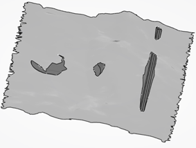
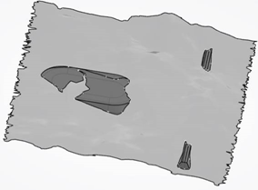
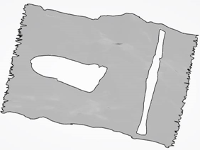
- Create modified terrain
- with excavations and fillings: By default, the option is
selected and you can see these modifications incrusted on the terrain.
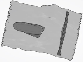
- with excavations: Only earthwork excavation stretches are
taken into account in terrain modification, filling stretches are ignored.
Consequently filling works are not computed.
- with fillings: Only earthwork filling stretches are taken
into account in terrain modification, excavation stretches are ignored.
Consequently excavation works are not computed.
- without excavations and fillings: the excavations and
fillings are removed from the modified terrain.
- with only excavations and fillings: The modified terrain
contains only excavations and fillings.
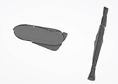
- with excavations and fillings: By default, the option is
selected and you can see these modifications incrusted on the terrain.
- Create excavation and filling works: when selected, excavation and filling works are created, or modified if they have already been created. If the option is not checked, they are deactivated.
- Keep non-connected excavation and filling works: To keep/remove excavation/filling works which are not connected to road/railway/platform surface.
- Create modified terrain
-
To modify a terrain, select it and the necessary inputs, except for subgrade layers
that are used to create consolidated subgrade layers. See the list and the associated
commands below.
If an input is selected outside the result stretch set, it is not moved into the result stretch set.
Only subgrade and stretch are editable. For other elements, the icon is disabled.
You cannot modify typed inputs. The last user-selected Type is proposed in the third column of the dialog box. For the first time, Excavation is proposed.
Element Editable Type and Remarks Earthwork Yes, click  .
.Earthwork Subgrade Yes Subgrade. UDF typed as Earthwork or Subgrade No The UDF main result must be typed as subgrade layer, or road/railway earthwork.
The earthwork/subgrade consistency check is applied:
- If the UDF main result contains a road/railway earthwork, you expect to have at least one excavation or filling works.
- It is forbidden to have more than one excavation work or filling work in the UDF.
- Optionally, the outputs may contain other subgrade layers.
Other UDF No The UDF main result is not typed or typed differently from what is described above.
They will be used as individual inputs.
If the selected UDF main result or output is typed as excavation works, it will be used as excavation inputs. The same for filling works.
Otherwise, you can choose it as excavation or filling input.
Excavation geometrical element No Excavation. It must have been typed as Excavation works. Filling geometrical element No Filling. It must have been typed as Filling works. Non-typed geometrical inputs (an open or closed surface, or a volume) No Excavation or Filling. A user-defined feature can contain outputs. You can create a user-defined feature from stretch/subgrade, or from any other surfaces/volumes/solids. There are two cases:
- The UDF main result must be typed as subgrade layer, or road/railway earthwork.
This case is considered as earthwork/subgrade. The earthwork/subgrade consistency
check will be applied:
- If the UDF main result contains a road/railway earthwork, you expect to have at least one excavation or filling works.
- If it contains a road/railway earthwork, you must have at least one excavation or filling works.
- It is forbidden to have more than one excavation works or filling works in the UDF.
Notes:- If inconsistency is found, an error or warning message is raised, according to the error maturity.
- In this case, you cannot select an output of this user-defined feature as an individual excavation/filling.
- The main result is not typed or typed differently from what is described above. In
this case, the main result and the outputs of the user-defined feature will be used
as individual inputs.
If it is typed as excavation works, it will be used as excavation inputs, without the possibility to modify it. This is the same for filling works.
Otherwise, you can choose it as an excavation or filling input.
An input is used as excavation works during the stretch set creation. During edition, if you change its type to filling, an error appears, and vice-versa. For example: If an output of case 2 is typed as road/railway stretch or subgrade layer, you still can select it as excavation or filling inputs.
Notes:- If the main result or an output of a user-defined feature is typed as subgrade layer, an object type must be associated to it to be taken into account in the global subgrade layer computation. The same rule applies to the outputs of subgrade outputs.
- During edition, if an input of the main result changes from case 1 to case 2, an error occurs during update. First, you declare it as earthwork/subgrade during the stretch set creation. Then you edit the user-feature type and change it as a non-earthwork/subgrade, which is inconsistent with what you planned to do.
-
To define the role of a surface (as excavation or filling in terrain modification) when
it is used in the Civil Set/Road
Set/Railway Set command, select the surface and click
Define Specification
 from
the Civil Engineering section of the action bar.
If the surface is specified as Excavation works or Filling works, its role is
automatically determined when it is selected in terrain modification.
-
To remove an element from the stretch set, click
 .
.
If the removed element is an earthwork or subgrade, aggregated under the stretch set, it will be moved from the stretch set into the result node of the input’s discipline (Civil Engineering/Road/Railway node).
You can reframe, hide/show each input with the help of the contextual menu associated to the input.
- To apply the terrain modifications, click OK.
-
To make changes, double-click Civil Set.xx for example in the tree.
The Civil/Road/Railway Set dialog box is displayed, in which you can select the necessary inputs.
| See Also |
| More help on this topic |